|
Trigger Setup(quick)
|
|
1. Trigger mode
Trigger mode has Waveform trigger and Pattern trigger.
(1) Waveform trigger
In the UI of waveform trigger, clicking the button “Show the waveform area” and box choose waveform need to trigger, the Preview result as Figure 2.
|
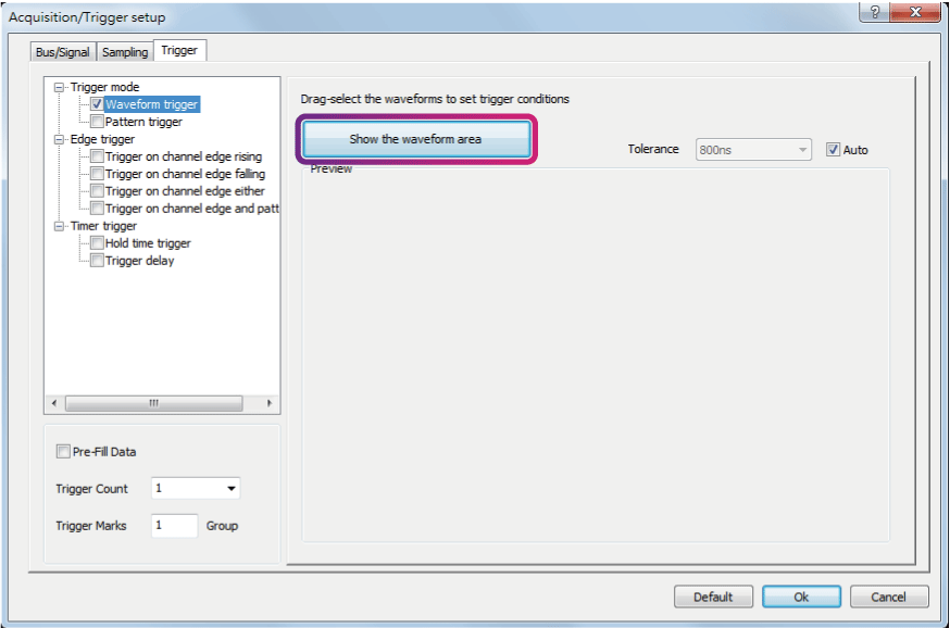
Figure 1:Waveform trigger dialog box
|
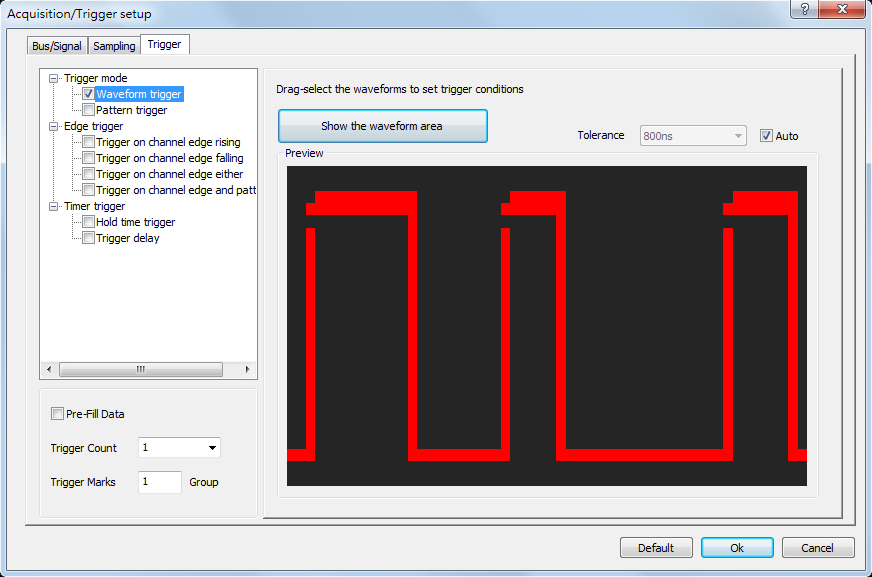
Figure 2:Waveform trigger preview dialog box
|
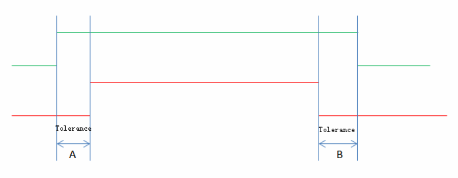
Select the triggered wave to trigger the wave in which high and low levels are in tolerance, the levels are shown: |
|
(2) Pattern trigger
In the UI of Pattern trigger, there can set the condition of Interval, Width, Wait for Bus or Signal shown as Figure 4 , Click ”Go To” can start Trigger or Next Pattern shown as Figure 5 . |
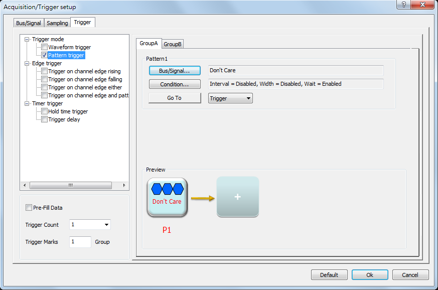
Figure 3:Pattern trigger dialog box
|
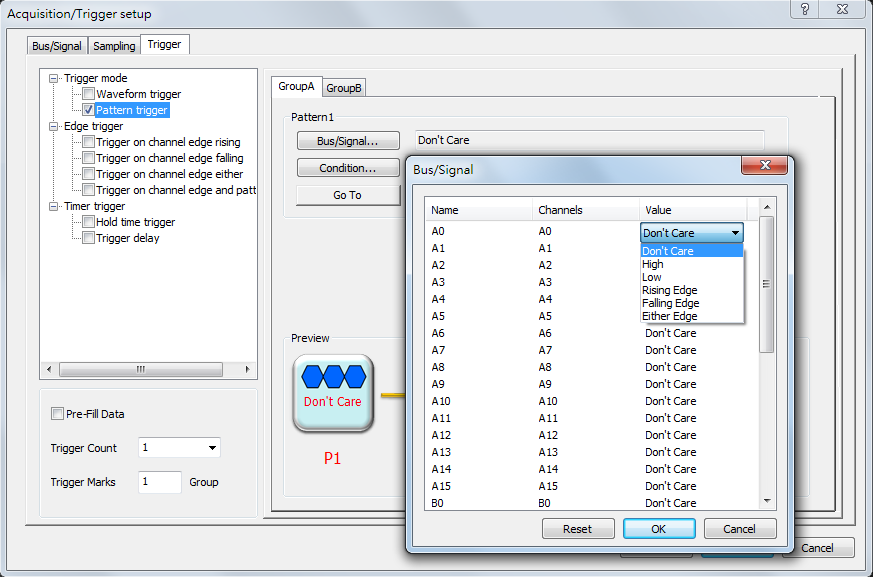
Figure 4:Bus/Signal dialog box
|
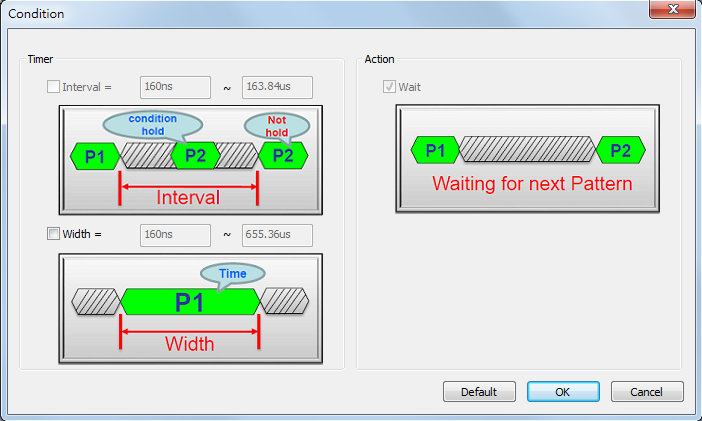
Figure 5:Condition dialog box
|
2. Edge trigger
Edge trigger have Trigger on channel edge rising, Trigger on channel edge falling, Trigger on channel edge either, and Trigger on channel edge and pattern.
(1) Trigger on channel edge rising
|
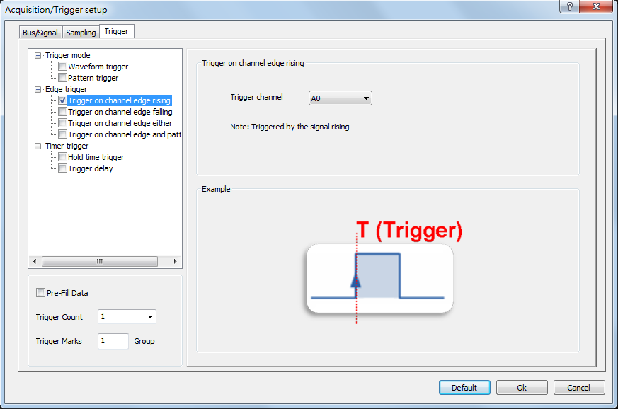
Figure 6:Trigger on channel edge rising dialog box
|
(2) Trigger on channel edge falling |
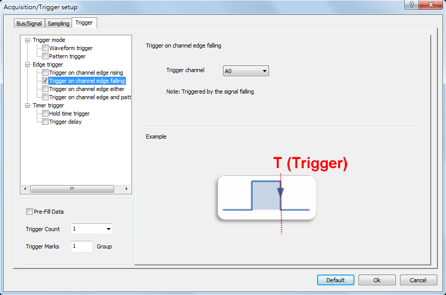
Figure 7:Trigger on channel edge falling dialog box
|
(3) Trigger on channel edge either |
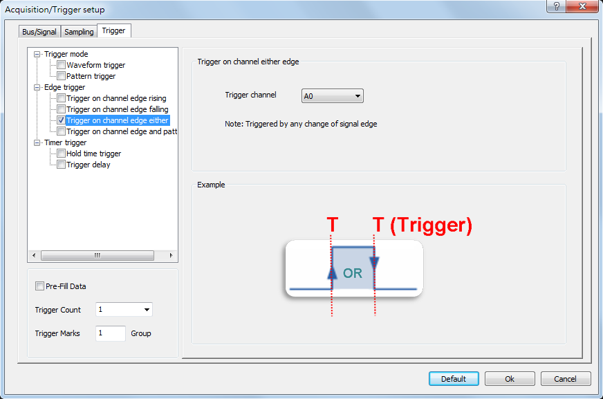
Figure 8:Trigger on channel edge either dialog box
|
(4) Trigger on channel edge and pattern |
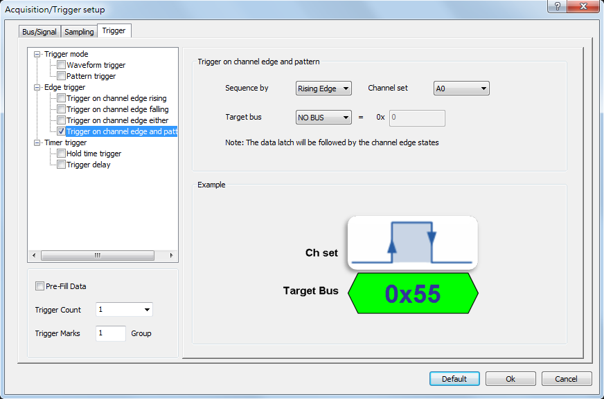
Figure 9:Trigger on channel edge and pattern dialog box
|
3. Timer trigger
Time trigger have Hold time trigger and Trigger delay.
(1) Hold time trigger
|
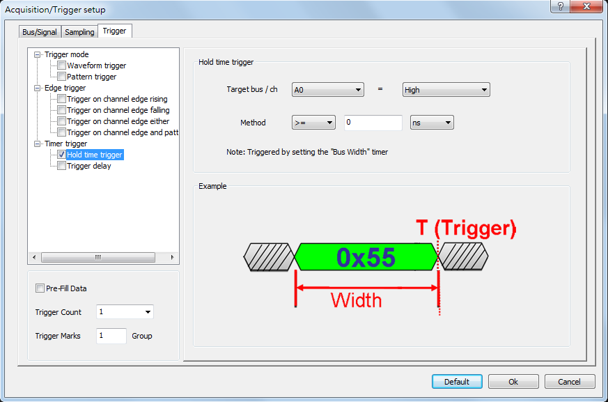
Figure 10:Hold time trigger dialog box
|
(2) Trigger delay |
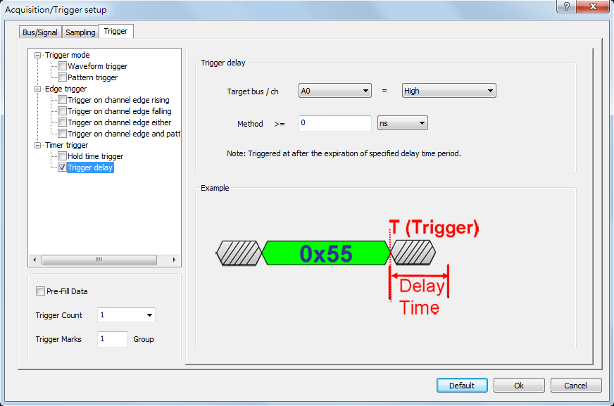
Figure 11:Trigger delay dialog box
|
|
Trigger Count
|
Trigger on the Xth event that satisfies the trigger conditions; at the default value of 1 the LAP-F1/2 will trigger on the first event.
Users can set to mark with trigger bar after the trigger condition is met for specified times(1-65535).
Set the trigger count to 1-3, below figures are their results:
|
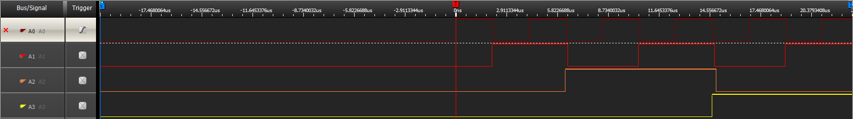
Figure 1:Set the trigger count to 1, the trigger condition to rising edge of A0. The Logic Analyzer will mark the first rising edge of A0 with trigger bar after it receives the signal.
|
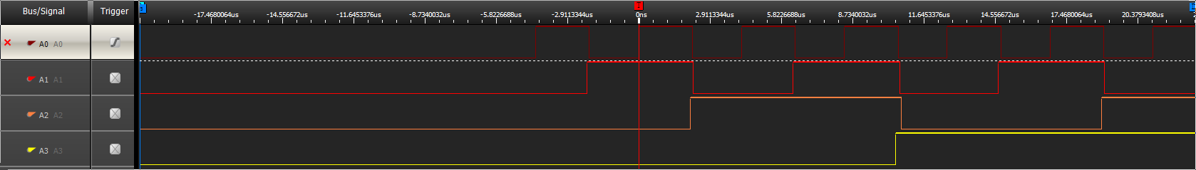
Figure 2:Set the trigger count to 2. Compared with the figure 1, the trigger bar is moved to the second rising edge of A0, that means this position is where the trigger condition is met for the second time.
|
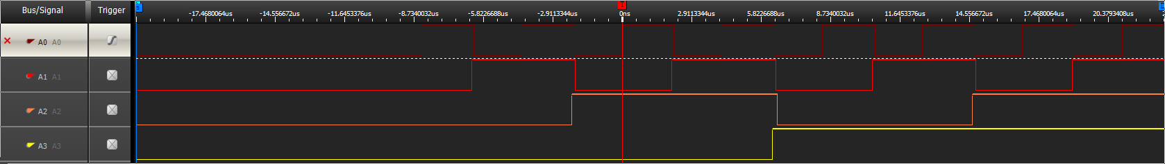
Figure 3:Set the trigger count to 3. Compared with the figure 1 and 2, the trigger bar is moved to the third rising edge of A0, that means this position is where the trigger condition is met for the third time.
|