 |
Level Trigger / Edge Trigger |
| It has six trigger conditions: Don’t Care, High, Low, Rising Edge, Falling Edge and Either Edge. |
Single Signal Trigger |
Users can set the trigger condition of each channel in the Single Signal Trigger Setting window, or set multi-level trigger, pulse width trigger, interval time trigger, etc.(Only B Series support). |
Protocol Analyzer Packet Trigger |
Users can set the packet as the trigger condition according to different protocol analyzer statuses, so as to trigger on the just position quickly and accurately. |
Trigger Content |
Users can set pre-trigger/trigger delay, trigger page, trigger level and other parameters in the Trigger Content window. |
Compression |
Compression is the patent technology of Zeroplus Technology. By its special compression algorithm, longer-time undistorted data can be acquired with the size-fixed memory. |
Filter |
It is a technology of waveform filtering, which can filter the unwanted waveforms. Work efficiency is improved if using it along with Filter Delay and Interval Bar. |
Filter Delay: |
It is the extension of filtering. Users can set the filter time by themselves. |
Interval Bar: |
With Filter activated, the Interval Bar can indicate the time and position of filtered waveform for users’ analyzing. |
Language |
Zeroplus Technology Logic Analyzer provides three interface languages: Chinese(Tr), Chinese(Si) and English. Users can select by themselves. |
Data Contrast |
According to the captured data, the Data Contrast can be used to analyze the contrasted results and mark the difference between the two files on the waveform display area. |
Bus Property |
Latch: Users can set the specified signal in the paralleling bus as the sampling site reference to analyze the data. |
Statistics |
It can display the quantity of positive period, negative period, full period, etc. in channel or set the time period to check if any period is out of the range. |
Capture |
Users can capture the waveform with self-defined range and save it in JPG or BMP format. |
| Waveform Unit Switching |
| Users can switch the value unit to time, frequency or sampling site. |
Noise Filter |
Users can filter the signal whose length is below some clock according to the sampling frequency. |
Add Bar |
Users can freely add the bar (128 at most) with different name. |
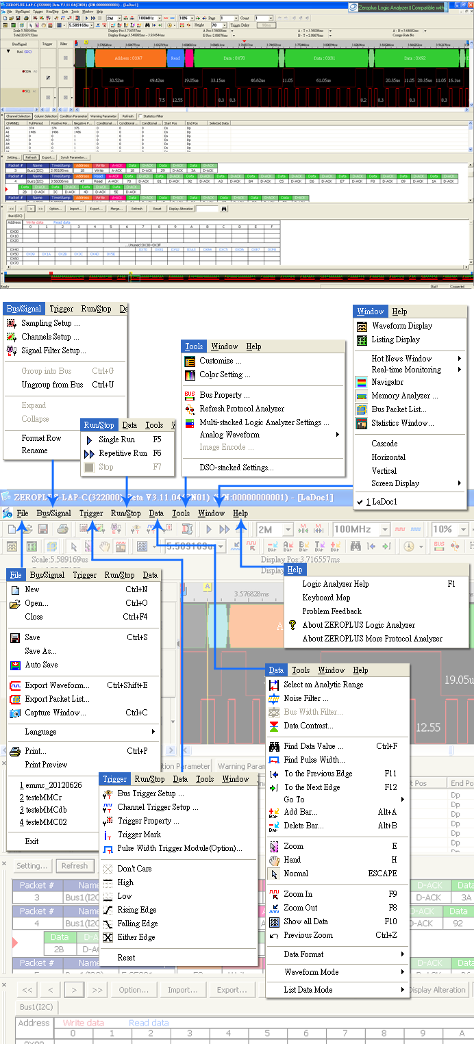
Customize |
Users can set the environment parameters by themselves. |
Bar Auto-close: |
When activated, the bar will auto-close the waveform edge if it is placed at the edge. |
Software Auto-update: |
After opened, the software will check whether there is any new version or not through internet. |
Auto Save: |
Zeroplus Logic Analyzer provides the Auto Save function. Users just need to set the time interval, then the software will auto-save the file after each interval. The software also can auto-save the complete captured data in repetitive run mode. |
Horizontal / Vertical Display |
The software can auto-adjust the size of windows and display them horizontally or vertically, so users can compare their data conveniently, such as the program difference between after and before modification. |
Bus Packet List |
| It can display the decoded protocol analyzer packets in a list for easy analyzing their statuses. |
Operating Systems |
| Windows 2000 / XP / Vista / Win7 |
Export Waveform |
| It can convert the waveform into the TXT File and CVS File. |
Hot News Window |
Engineers can get the latest activity and product information from this window which displays that in running text. |
Memory Analyzer |
| With it users can analyze the address, value or read/write status in the memory. |
Pulse Width Trigger Module (Optional) |
| The waveform width time can be set as the trigger condition. It is suitable for PWM signal checking, clock signal measuring, etc.. |
Screen Display |
It is suitable for the PC system that supporting two screens. Users can set the software be displayed in two screens or in the first/second screen. |
Bus Width Filter |
Error caused by asynchronous sampling may happen during measuring the bus value with internal clock. |
Navigator |
It is in the lowest position of software window, from which users can preview the data statuses in the memory. |
Multi-stacked Logic Analyzer Settings |
This function means that it can connect many Logic Analyzers of the LAP-C Series. In this way, it can increase the RAM Size or the number of the Channel; users can connect four Logic Analyzers at most. (not supported under 162000 models) |
Analog Waveform |
This function can display the value of each data by way of the curve mode on the waveform display area when users analyze the Protocol Analyzer, and users can judge that the data is correct or not according to the description of the Analog Waveform when they analyze the value of the Protocol Analyzer. |
Find Specified Data |
Users can quickly find the specified data, such as paralleling bus value, serial bus packet (I2C, UART, SPI…); and count how many data fitting the find condition in the waveform. |
Find Pulse Width |
Users can find whether there is any specified pulse width in the waveform, and count the quantity of pulse fitting the find condition. |
|
||||||||||||||||||||||
|