|
|
Maximum efficiency can only be achieved by excellent hardware and humanized software working together. In this file the software functions of Zeroplus Logic Analyzer are described in details with features emphasized. Zeroplus Technology provides good after-sale service and free complete training course. Welcome to contact us!
|
 (video - Basic Operation)
System Requirements
| Supported OS | Versions |
|---|
| Windows 10 |
32- and 64-bit (Recommended) |
| Windows 8.1 |
32- and 64-bit (Recommended) |
| Windows 7 |
32- and 64-bit |
| Windows Vista |
32- and 64-bit |
| Windows XP |
32-bit(Home、Professional Editions) |
| Windows 2000 |
Professional、Server series |
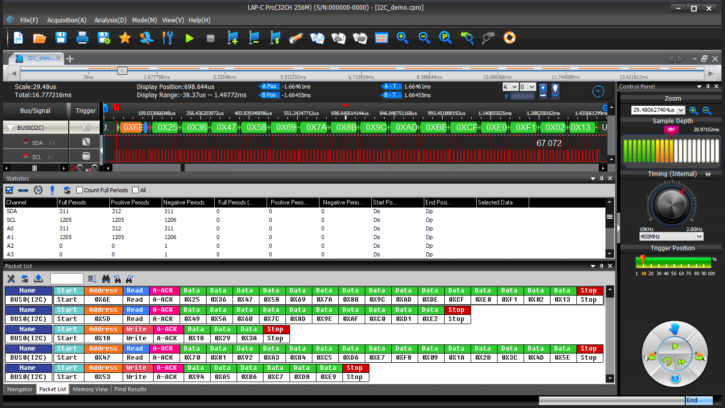
User Interface
Bus Triger
|
Users can set the packet as the trigger condition according to different protocol analyzer statuses, so as to trigger on the just position quickly and accurately.
|
Acquisition Setup
|
Acquisition/Trigger Setup choices such as channel assignment, Sampling mode and the Trigger Setup dialog box. This is also where users can adjust the voltage threshold for triggering and configure a DSO connection. |
Trigger Position
|
The trigger position determines which samples are stored. |
Statistics
|
It can display the quantity of positive period, negative period, full period, etc. in channel or set the time period to check if any period is out of the range. |
Sample Rate
|
The sample rate or acquisition frequency determines how often samples are taken.
|
Waveform Unit Switching
|
| Users can switch the value unit to time, frequency or sampling site. |
Add Bar |
Users can insert up to 250 additional bars. When adding a bar the user can select color and where it should be positioned (in time). The bars will automatically be named A0-A9, B0-B9 etc. |
Packet List |
| By presenting the packets in list form, the Packet List facilitates observation and analysis of all packets and their relation. Only packets under a protocol decoder can be displayed. |
Operating Systems
|
| Windows 2000,XP,Vista,WIN7,WIN8.1,WIN10. |
Sample Depth |
Determine the amount of data to be acquired per channel. |
trigger column
|
| It has six trigger conditions: Don't Care, High, Low, Rising Edge, Falling Edge and Either Edge. |
Menu
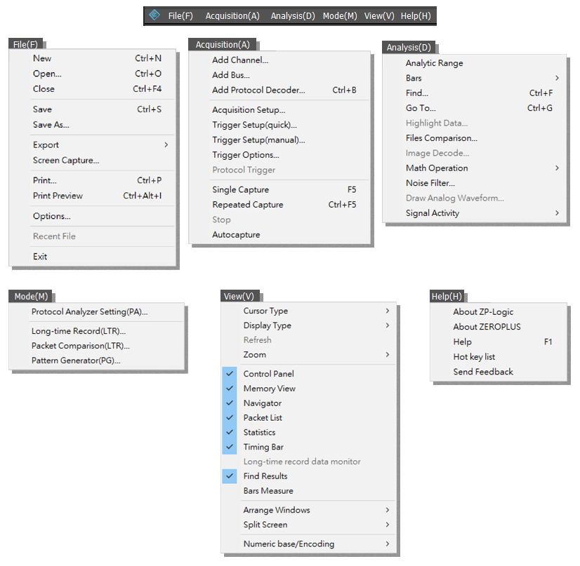
Export
|
| Users can choose between three types of exports: Waveform, Packet List or Memory View. |
Screen Capture |
Select a part of the screen – or all of it – and store it as a file or a picture. |
Trigger Setup(quick)
|
1. Trigger mode
Trigger mode has Waveform trigger and Pattern trigger.
2. Edge trigger
Edge trigger have Trigger on channel edge rising, Trigger on channel edge falling, Trigger on channel edge either, and Trigger on channel edge and pattern.
3. Timer trigger
Time trigger have Hold time trigger and Trigger delay.
|
Trigger Setup(manual)
|
Trigger Setup (manual) offers settings as the following figure with multiple levels triggering, trigger wait, trigger delay and so on. |
Trigger Options
|
Adjust trigger properties such as Trigger Position and Trigger Delay. |
Analytic Range |
Adjust the analysis range by adjusting the position of the so-called Ds and Dp bars. |
Bars
|
The ZP-Logic Waveform / State List areas come with 5 standard bars (these are sometimes referred to as Cursors). The bars delimit the analysis range and facilitate navigation and observation. |
Find
|
Post acquisition, Find is used to look up events that satisfy a set of user-defined conditions. There are Advanced Find and Easy Find. |
Math Operations
|
Create a new trace by performing a mathematical operation on two existing signals. |
Noise Filter
|
The Noise Filter is used to filter out short-lasting pulses or dips in signals that the user considers to be noise. |
Signal Activity
|
Signal Activity offers the user real-time views of what the probes are seeing. Two modes are available; Real-time Frequencies and Signal Status. By means of these functions the LAP-C Pro monitors signal frequencies and states, thus assuming the function of a frequency counter and that of a logic pen. |
Long time Record
|
The Long-time Record (LTR) function lets the user stream data directly to the computer over USB3.0, thus allowing much longer acquisitions than during normal operations when the samples are stored in the LAP-C Pro’s internal memory. |
Pattern Generator
|
The Pattern Generator generates digital signals through 4 channels. Support mainstream bus and GPIO such as I2C, SPI, UART, CAN, etc. Need to import the provided Excel file. |
Long-time record data monitor
|
The LTR Monitor window is used to monitor the data transfer between the DUT and the computer when using the Long-time Record function. |
Split Screen
|
If more than one screen is connected to the computer ZP-Logic is running on, users can choose to show ZP-Logic on either one of the screens or on both. |
|
|
|