|
Pre-trigger/Delay-trigger
|
Users can decide to analyzer the status before the trigger happens or the data after the trigger happens plus specified time.
Pre-trigger :
Users can set the trigger position in percentage to display the status before trigger happens. See figure 1, the trigger position is set as 90%, that’s mean only 10% of memory is used to store the status after trigger, 90% is for the status before trigger. |
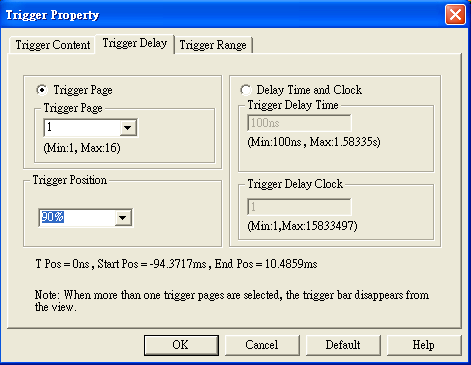
Figure 1: The trigger position is set as 90%.
|
Set the trigger condition of one group of paralleling bus as 0X5A, and set the trigger position as 90%, then start capturing. The Logic Analyzer will display the data before 0X5A. (See figure 2) |
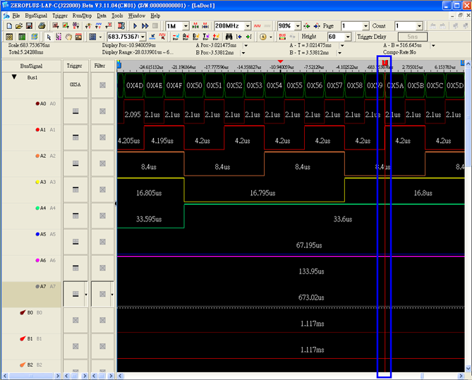
Figure 2: The trigger condition is 0X5A and the trigger position is 90%.
|
Delay-trigger :
The Logic Analyzer can capture the waveform after the trigger happens plus the delay time set by users. See figure 1, input the delay time(50us) in the window and press “Enter” to start capturing, then the Logic Analyzer will display the waveform after trigger happens plus 50us. |
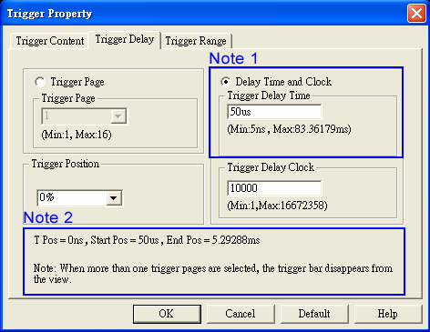
| Note 1: |
In this position users can input the delay time. Below this position are the max. time and min. time determined by the current memory and sampling frequency. |
| Note 2: |
This information includes time display of trigger bar position, start position and end position according to the current delay time. |
|
Figure 2 is the waveform with trigger condition of 0X5A and trigger delay of 50us. |
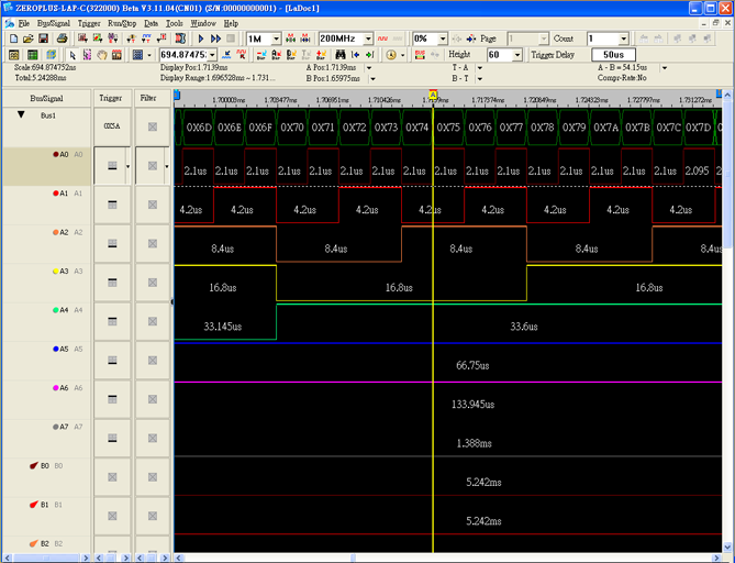
Figure 2: Set the trigger condition as 0X5A, and trigger delay as 50us.
|

|
 (video - Trigger Page) (video - Trigger Page) |
This function can divide the long signal into pages for capturing and analyzing.
For example: Use the Up Count to capture the signal, and set the memory of each page as 2K, then the waveform will be displayed as below: |
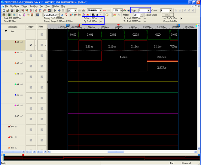
Figure 1: Memory is 2K, Page 1. The end time is 9.225us.
|
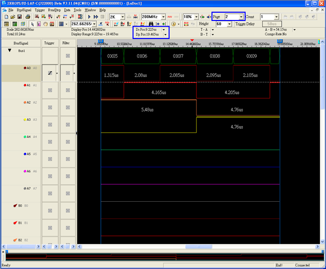
Figure 2: Memory is 2K, Page 2. The start time is 9.225us; the end time is 19.465us.
|
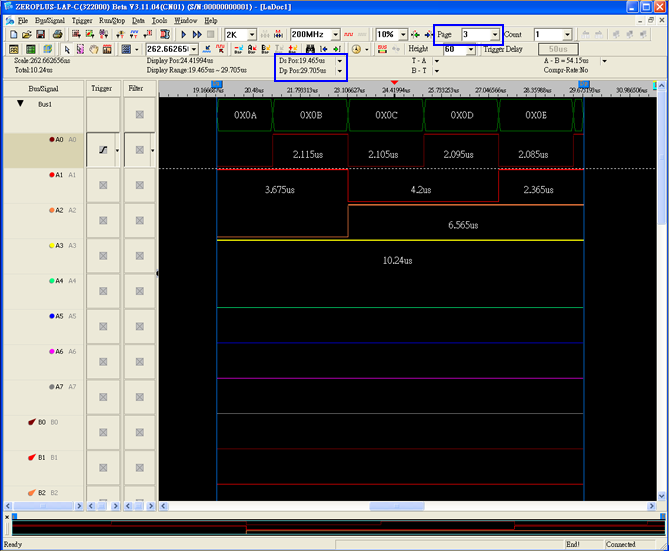
Figure 3: Memory is 2K, Page 3. The start time is 19.465us, the end time is 29.705.
|
Under the same trigger condition, users can use the trigger page function to capture the whole signal in many times. The data in each page is continuous, that will help users to do long-time analyzing. |
|
Users can set to mark with trigger bar after the trigger condition is met for specified times(1-65535).
Set the trigger count to 1-3, below figures are their results:
|
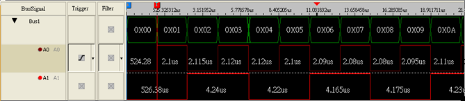
Figure 1: Set the trigger count to 1, the trigger condition to rising edge of A0. The Logic Analyzer will mark the first rising edge of A0 with trigger bar after it receives the signal.
|
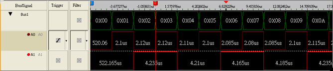
Figure 2: Set the trigger count to 2. Compared with the figure 1, the trigger bar is moved to the second rising edge of A0, that means this position is where the trigger condition is met for the second time.
|
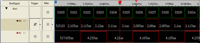
Figure 3: Set the trigger count to 3. Compared with the figure 1 and 2, the trigger bar is moved to the third rising edge of A0, that means this position is where the trigger condition is met for the third time.
|
|
|