|
- Bit Rate: Set the transmission rate between SPI Master and Slave. There are 156, 312, 625, 1250, 2500, 5000 and 10000KHz to choose.
- MOSI(Master Output Slave Input) Data Write: The input format is hexadecimal. The data can’t exceed 10240 bytes because of the Buffer limitation.
- Write: Press the Write button to write the data in the MOSI into the Slave Device.
- CPOL: It can be set as Rising/Falling, or Falling/Rising.
- CPHA: It can be set as Sample/Setup, or Setup/Sample.
(CPOL and CPHA are parameters in the SPI Mode, users can do necessary adjustment).
- Bit Order: Set the transmission direction as MSBLSB or LSBMSB.
- SS Polarity: It is divided into SS Active Low and SS Active High. Only the SPI Master end can be set, the SPI Slave end is fixed in SS Active Low.
SPI takes full duplex transmission. The MISO receives the data as soon as the MOSI transmits it; the Message length is the same. |
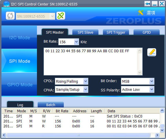
Figure 1: SPI Master Interface
|
|
- MISO(Master Input Slave Output) Data Responding: The input format is hexadecimal. The data can’t exceed 64 bytes because of the Buffer limitation.
- CPOL: It can be set as Rising/Falling, or Falling/Rising.
- CPHA: It can be set as Sample/Setup, or Setup/Sample.
(CPOL and CPHA are parameters in the SPI Mode, users can do necessary adjustment).
- Bit Order: Set the transmission direction as MSBLSB or LSBMSB.
- Enable/Disable: When the button is enable, data will be returned to the Master end. When the button is disable, then CPOL, CPHA, Bit Order and Returned Data can be set.
|
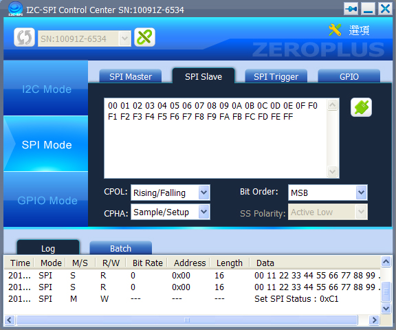
Figure 2: SPI Slave Interface.
|
|
- Condition1/Condition2: MOSI Data, MOSI Data(First), MISO Data and MISO Data(First) can be set. If the Condition2 is set as None, then only one condition can be set for the Condition1.
- Count: Set the times that the condition shall be met to make the trigger happen.
- Continuity: Judge the two conditions need to be judged continuously or not.
|
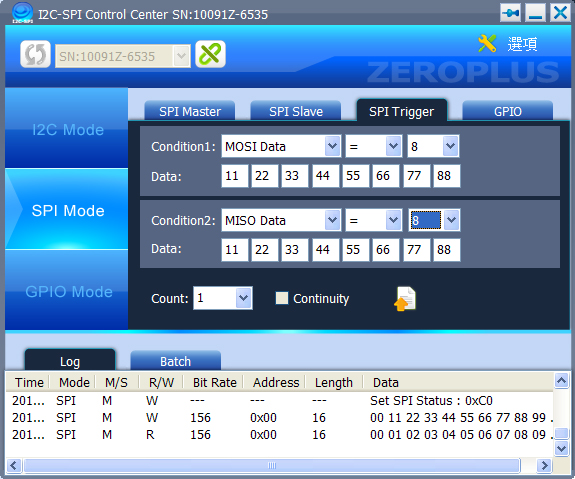
Figure 3: SPI Trigger Interface
|
|
- Direction: Set the pin to be In status or Out status.
- Pull up: Judge the pull up resistance is needed to add to the pin or not. It only can be set in In status.
- Out Set: Set the Out status of this pin, then press “Set” key to output the value.
- In Value: Press the “Get” key to detect the status of each pin.
|
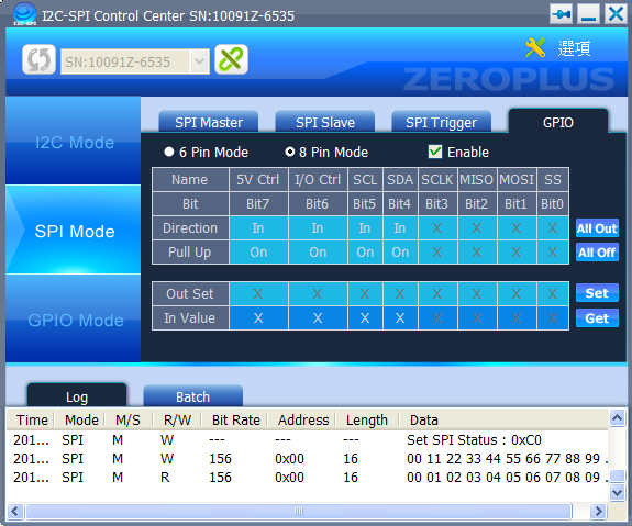
Figure 4: SPI GPIO Interface.
|
|
|
|