|
|
|
- Slave Address: Set the address of Slave Device in hexadecimal.
- Read Bytes: Set the data byte quantity read by the Master from the Slave Device.
- Bit Rate: Set the data rate.
- 10-Bit Address: Set the address mode of Master Device, which is 7-bit address by default.
- Combined Format: Set the I2C Master to use the Combined Format or not.
- No Stop: The I2C Master doesn’t send the Stop after the data transmission ends and still keeps the current Read/Write status.
- Write: Press the Write button to write the data into the Slave Device. 1024 bytes data can be written at most.
- Read: Press the Read button to read data from the Slave Device.
- Write Message: The transmitted data during writing of the Master Device. It is hexadecimal.
|
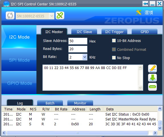
Figure 1: I2C Master Interface.
|
|
- Slave Address: Set the data address of the Slave Device. It is hexadecimal and in the range of 0-7F.
- Respond Bytes: Set the largest transmission bytes of the Slave Device, which shall not exceed 65535 bytes. It has no limitation if it is set to 0 (if the Respond Byte is more than the Respond Message, then the Respond Message will be transmitted repetitively).
- Respond Message: The data returned from the Slave Device. It is hexadecimal and not exceed 64 bytes.
- Enable/Disable: The button is enable means the Slave Device is working. If it is disable, then the Slave Address, Respond Bytes and Respond Message can be set.
|
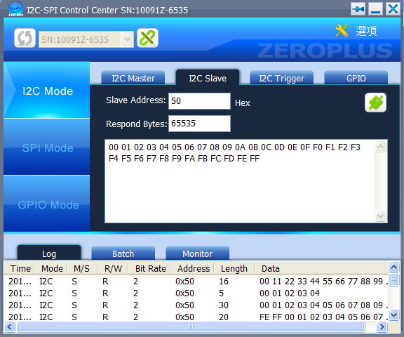
Figure 2: I2C Slave Interface.
|
|
- Condition1/Condition2: There are Write Data, Read Data, Write Data(1st) and Read Data(1st) can be set for the Condition.
- Count: Set the times that the condition shall be met to make the trigger happen.
- Continuity: Judge the two conditions need to be judged continuously or not.
|
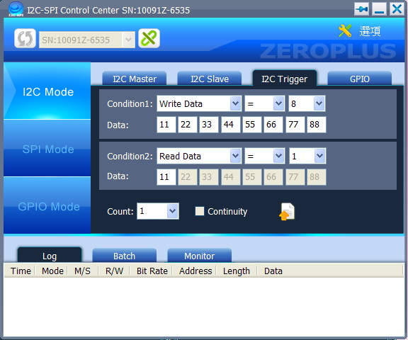
Figure 3: I2C Trigger Interface.
|
|
- Direction: Set the pin to be In status or Out status.
- Pull up: Judge the pull up resistance is needed to add to the pin or not. It only can be set in In status.
- Out Set: Set the Out status of this pin, then press “Set” key to output the value.
- In Value: Press the “Get” key to detect the status of each pin.
|
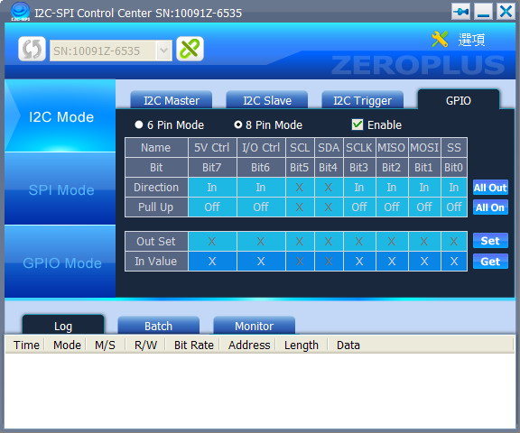
Figure 4: I2C GPIO Interface.
|
|
|
|
|