Logic Analyzers-Zeroplus


  youtube facebook twitter  
  Instrument Division
繁體中文 / 简体中文 / English  
Software
   >>Signal Process Home / LAP-C Standard /
 Trigger Function
 Signal Process
 Other
 I2C-SPI Control Center
- Filter Delay / Interval Bar -


Filter Delay (Taiwan Patent No. I 271532)

How to set conditions to acquire more effective signal in the long capturing.

(video - Filter Function and Filter Delay)

Do you meet the occasion that much acquired data is not you want? Now with “Filter and Filter Delay” function, users can set the high/low level in the signal as the filter condition, and set the filter delay time, so as to capture the needed data.

Users only need to set the conditions properly, then they can quickly find the needed signal in the long signal, much trouble is avoided.

Application: If some wireless project has some connection problem, since most data transmission is in the air, so it is no need to capture the waveform. If users only need to know the waveform after some command happens plus about 100us, then they can use the Filter Delay function to just acquire the important waveform; in this way much time and memory is saved.

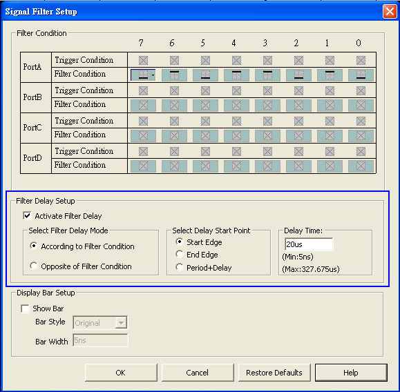
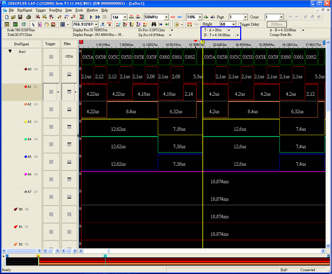
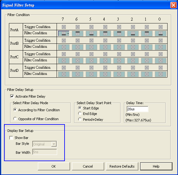
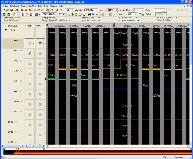
For example: For an object under test, the write command is 0X5A, and its time cycle is 5us; then users can set the “Filter Delay” to make the Logic Analyzer capture 20us after 0X5A happens. See figure 1 for the setting interface, figure 2 for actual waveform.

Figure 1: Filter delay setting window.


Figure 2: Only 20us after 0X5A is captured. Users can see the time relation from T bar and A bar.

Figure 2: T - A = 20us , B - T = 4.34188ms


Filter Interval Bar

This function is designed by Zeroplus Technology specially for users’ convenience. The filter interval bar can clearly mark the filtered time range.

Figure 1 shows the filtered waveform with the condition of A0 be high.

Figure 1: Set the filter condition as A0 be high.


In figure 1, since only the high level be captured in A0 channel, so it is all high level in A0 channel.

In the filter interval bar setting window (see figure 2), users can set the interval bar as Original or Bar. Original means the filter time is displayed completely; Bar can be used along with the time width to avoid the filter range be too large and affect the display range (see figure 3).

Figure 2: Filter interval setting window.


Figure 3: The image after filter interval bar activated (the interval bar is set as Bar with width of 1us).


Copyright ZEROPLUS TECHNOLOGY CO., LTD.