|
| [2025-06-17] |
Understanding EtherCAT: Complete Decoding from MII Packets to Timing Analysis |
|
EtherCAT Communication Architecture and MII Digital Interface Overview
EtherCAT is an industrial real-time communication protocol based on standard Ethernet. It utilizes the IEEE 802.3u-compliant 100BASE-TX physical layer (PHY) with a transmission speed of 100 Mbps and supports full-duplex communication, enabling simultaneous data transmission and reception. Despite the full-duplex capability at the physical layer, the EtherCAT protocol handles data as a logically "unidirectional chain," enhancing communication efficiency and reducing latency.
This streamlined physical and logical architecture allows EtherCAT to deliver high-performance real-time communication while maintaining compatibility with existing industrial Ethernet infrastructure, offering a stable and efficient solution for industrial automation.
The EtherCAT frame structure is based on the Ethernet II format, comprising three major sections: the Ethernet Header (containing Destination MAC, Source MAC, and EtherType 0x88A4), the EtherCAT Data (which includes one or more EtherCAT Datagrams with fields such as command, address, data, and Working Counter), and the FCS (Frame Check Sequence) for error checking. This design enables the EtherCAT master to transmit frames that pass through all slave devices “on the fly,” achieving high-speed, real-time communication.
MII (Media Independent Interface) plays a critical role in EtherCAT’s real-time communication system by enabling low-latency and highly synchronized data exchange. Operating at 10/100 Mbps full-duplex, MII is the standard interface between the digital controller and the PHY layer, supporting simultaneous data transmission and reception.
When the EtherCAT Slave Controller (ESC) connects to the Ethernet PHY through MII, EtherCAT frames are transferred between the ESC and PHY over the MII channel. The ESC uses an on-the-fly processing mechanism to receive incoming packets directly from the PHY without buffering the entire frame. It extracts and processes necessary data before forwarding the packet to the next PHY via another MII connection. This architecture ensures efficient, real-time forwarding and data exchange of EtherCAT packets. As such, MII is the core hardware interface for EtherCAT packet transmission between the ESC and the physical layer, playing a pivotal role in overall communication efficiency and real-time performance.
|
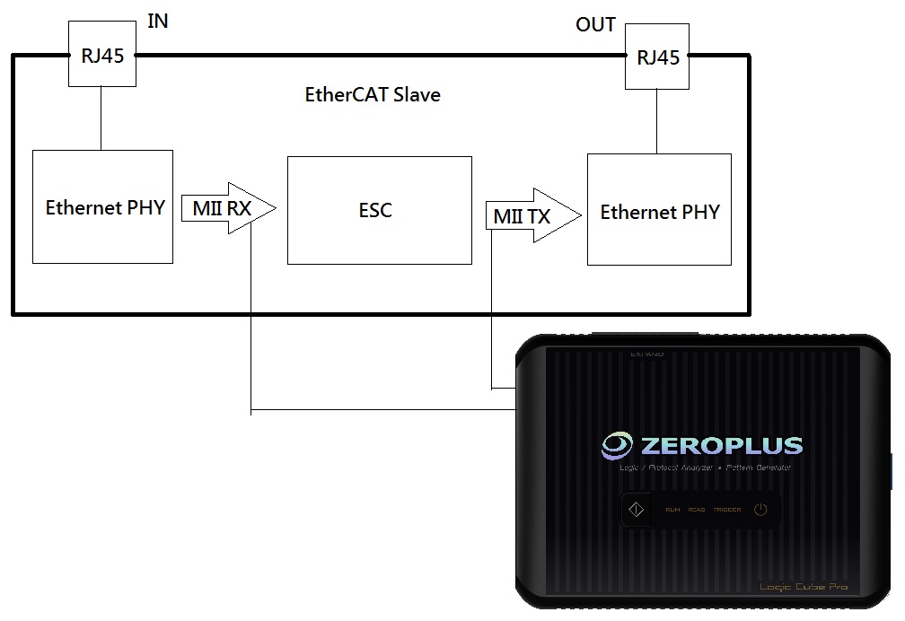 |
EtherCAT:Slave Environmental Measurement Schematic
MII Testing and Logic Analyzer Applications
Test Objective
Using the ZEROPLUS logic analyzer, we conducted timing and packet analysis of the ESC’s MII interface. The analysis includes:
- Verification of MII signal timing and waveform accuracy
- Synchronization between data bits and control signals
- Conformance of EtherCAT packet data to protocol specifications
- Evaluation of response latency and data integrity |
 |
Test Method (EtherCAT Packet Decoding and Analysis)
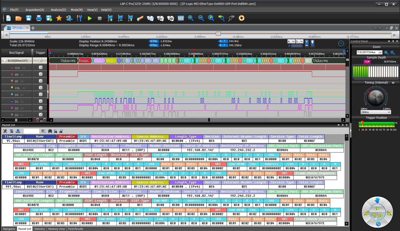
Throughout the testing process, the logic analyzer's built-in EtherCAT protocol decoder was employed to thoroughly capture and analyze MII signals between the ESC and PHY. Key test features include:
- EtherCAT Packet Decoding: Clearly identifies command type, address, length, and data content for comprehensive data interpretation
- MII Timing Analysis: Examines synchronization between TX/RX signals, CLK, EN, DV, and data bits
- Data Consistency Verification: Compares write and read-back status registers to ensure transmission accuracy
- Packet List Analysis: EtherCAT packets are decoded and listed, matching waveform signals. This enables rapid identification of data sources and error points, minimizing the need to reference protocol specifications manually
In the development and validation of EtherCAT systems, the ZEROPLUS logic analyzer provides not only data but reliable evidence of the system’s actual operational behavior. |
|
|
|