|
PC System
 |
|
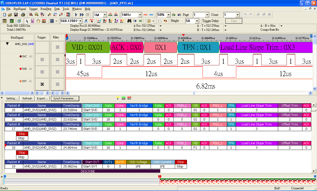
AMD Serial VID Interface 2.0 (short for SVI2), an interface designed by AMD, has a structure similar to that of I2C and two channels: CLK and DATA. It is mainly applied to the voltage control between CPU and Northbridge chip for adjusting the voltage according to the load status of CPU, so as to make the power be supplied more efficient. |
|
|
 |
|
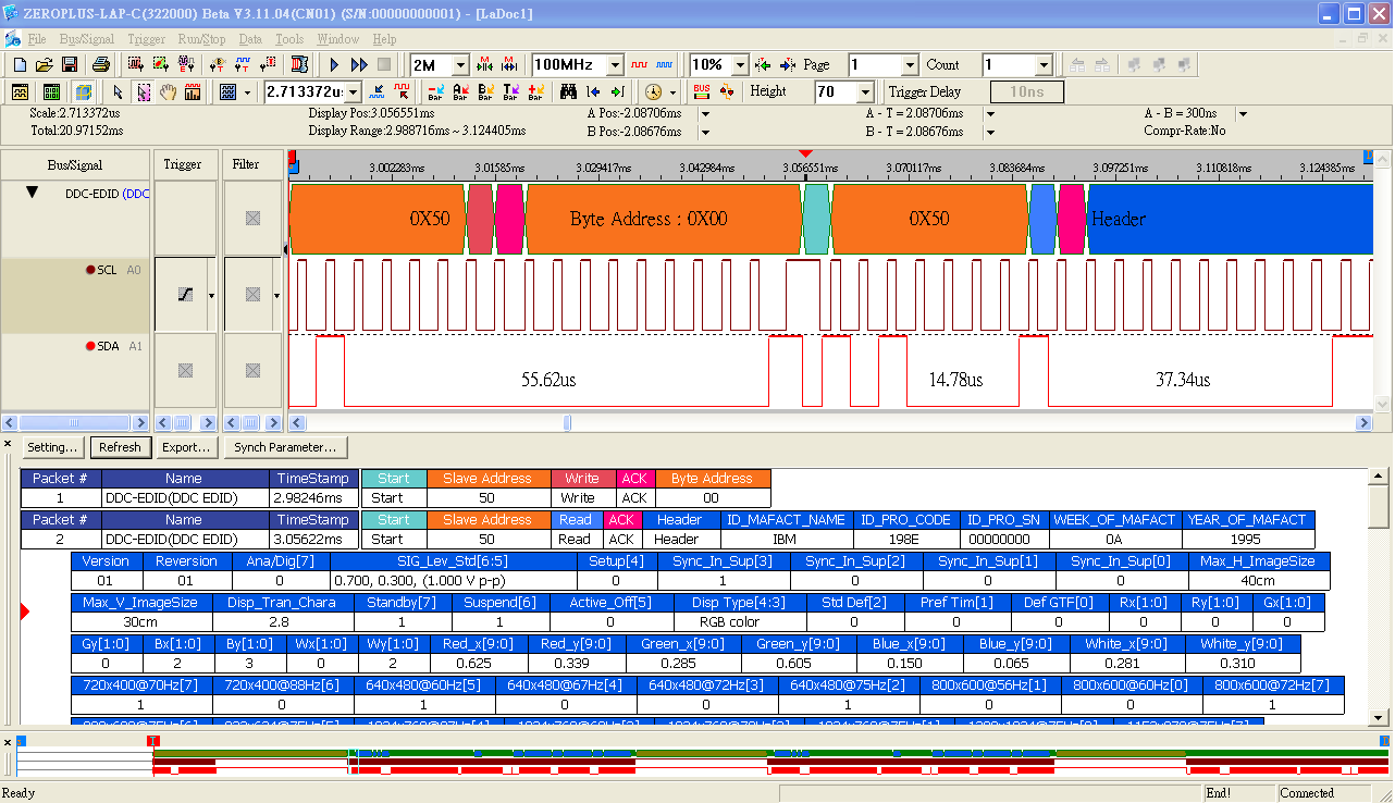
DDC, short for DISPLAY DATA CHANNEL, is a standard protocol for communication between display and host. It can transmit the information about the display, such as acceptable frequency range, manufacturer, production date, serial No., model, standard display mode and its parameters, supported DDC standard types, EDID versions, etc. to the host. DDC standard protocol of high version allows the host to adjust the basic parameters of display, such as luminance, contrast, central position, color temperature parameters, etc.. |
|
|
 |
|
 (Video Intro – How to measure the eSPI Bus) Intel has developed a successor to the low pin count (LPC) bus called the Enhanced Serial Peripheral Interface Bus (eSPI). Compared with systems using LPC, Intel hopes to reduce the number of pins required on the motherboard, with higher available throughput than LPC. This video introduces users to record and decode eSPI signals. And export the package list to a text file. (Video Intro – How to measure the eSPI Bus) Intel has developed a successor to the low pin count (LPC) bus called the Enhanced Serial Peripheral Interface Bus (eSPI). Compared with systems using LPC, Intel hopes to reduce the number of pins required on the motherboard, with higher available throughput than LPC. This video introduces users to record and decode eSPI signals. And export the package list to a text file. |
|
|
 |
|
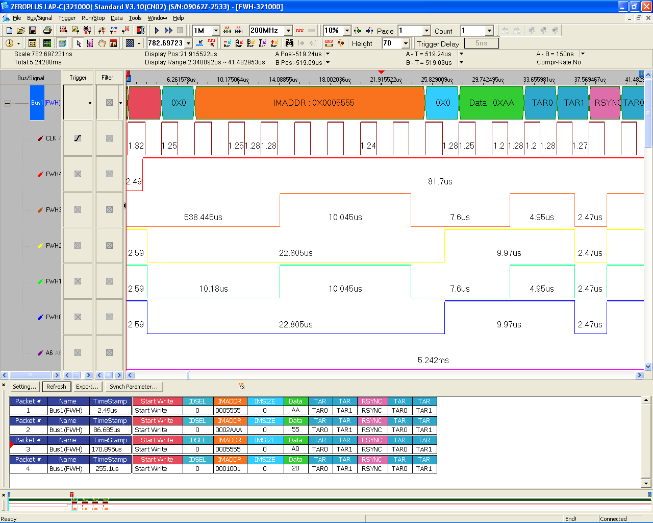
FWH (Firmware Hub), instituted by Intel, is kind of Device Protocol (Intel Product Code: 82802). It mainly uses the internal Flash Array Device to store the Data and communicates with the ICH through the LPC/FWH protocol. And it can support 16 FWH Devices at most, which will reduce the Pin Count from the BIOS to the Flash ROM greatly. |
|
|
 |
|
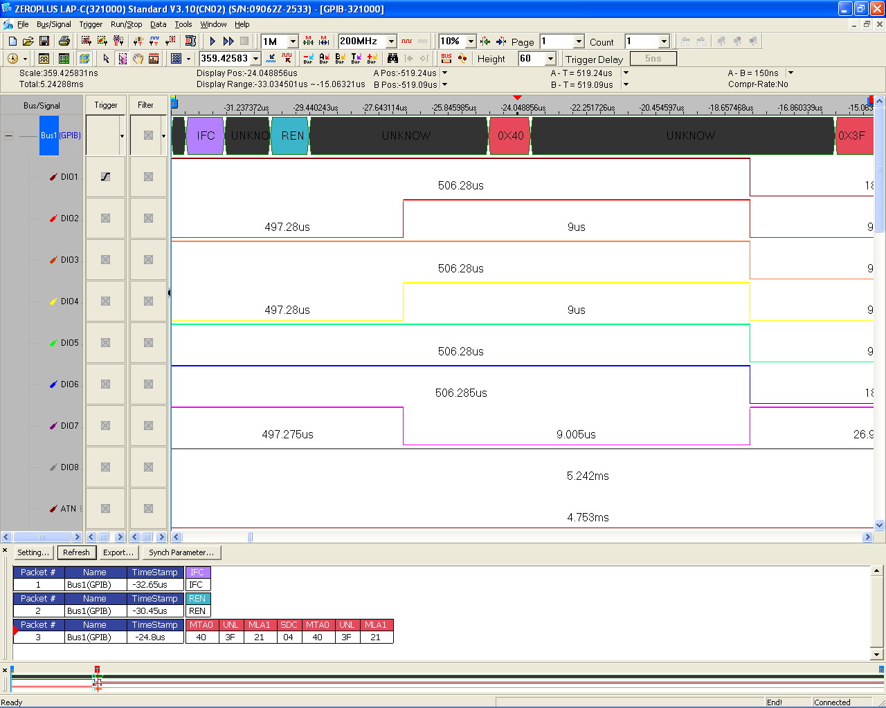
GPIB(General-Purpose Interface Bus)is a kind of the most common Device Communication Interface. It was developed by HP in 1965 and named as HP-IB at first. Until 1975, the HP-IB was defined as an IEEE-488 Standard by the IEEE Association and renamed as GBIP. In 2003, the IEEE-488 was updated to the IEEE-488-2003 and defined the 8-bit Digital Parallel Communication Interface. So the Transmission Speed can be up to 8Mbps, the distance of the cable can be up to 20m and fourteen Devices can be connected at most. |
|
|
 |
|
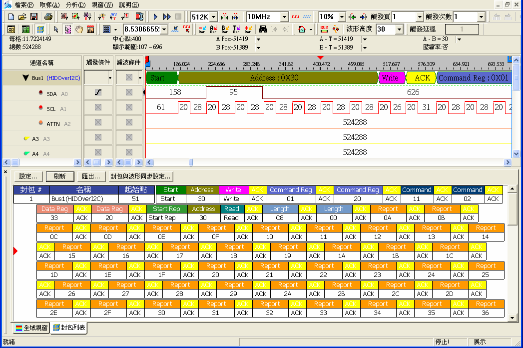
The development and application of HID is in USB and bluetooth at first, for Windows 8, Microsoft created a new HID mini port driver, that make the equipment communicate in an internal internal integrated circuit. I2C is an extremely simple, high efficient, low power protocol, and have been used in mobile and embedded platform more than ten years. |
|
|
 |
|
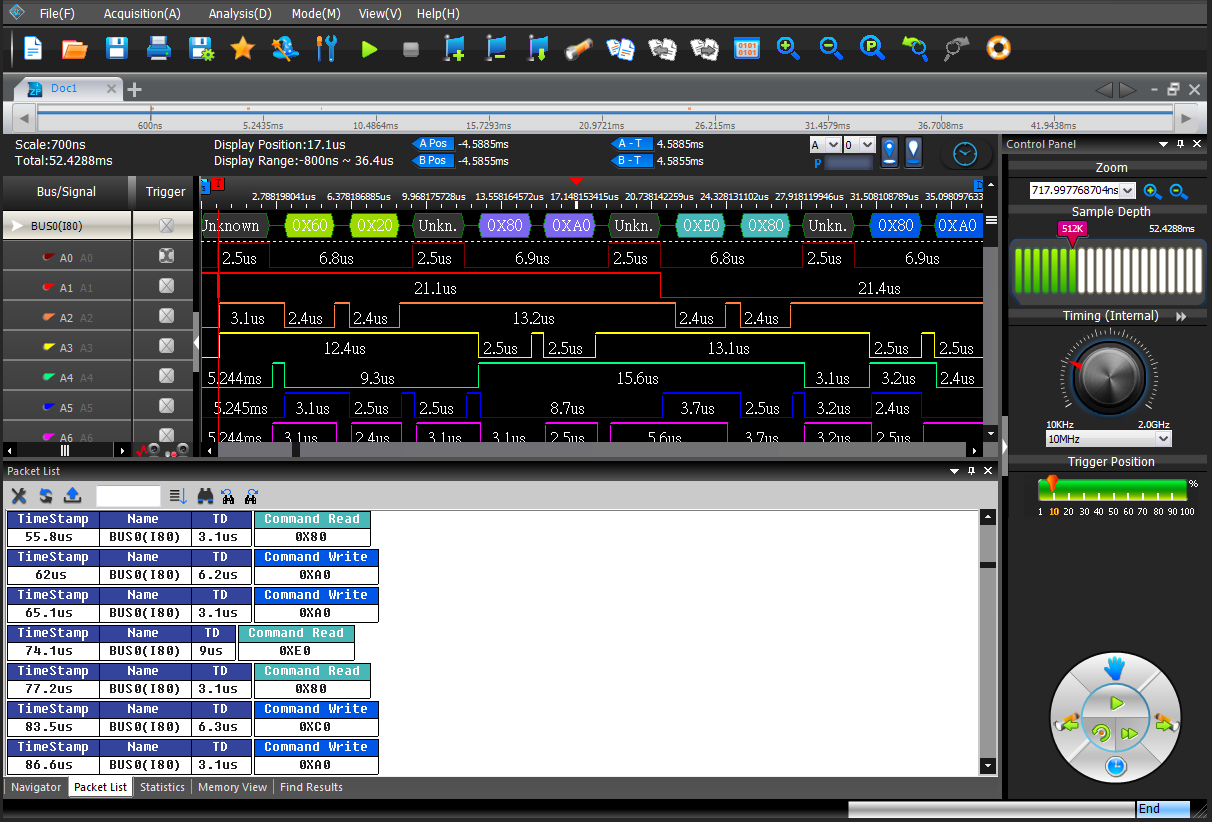
I80 (Intel 8080) bus is also called the Intel bus, Intel 8080 was released early in 1974,Intel processors,I80 bus is 8080 processor on the integration of parallel interface connection mode,already developed now become general parallel transmission mode. |
|
|
 |
|
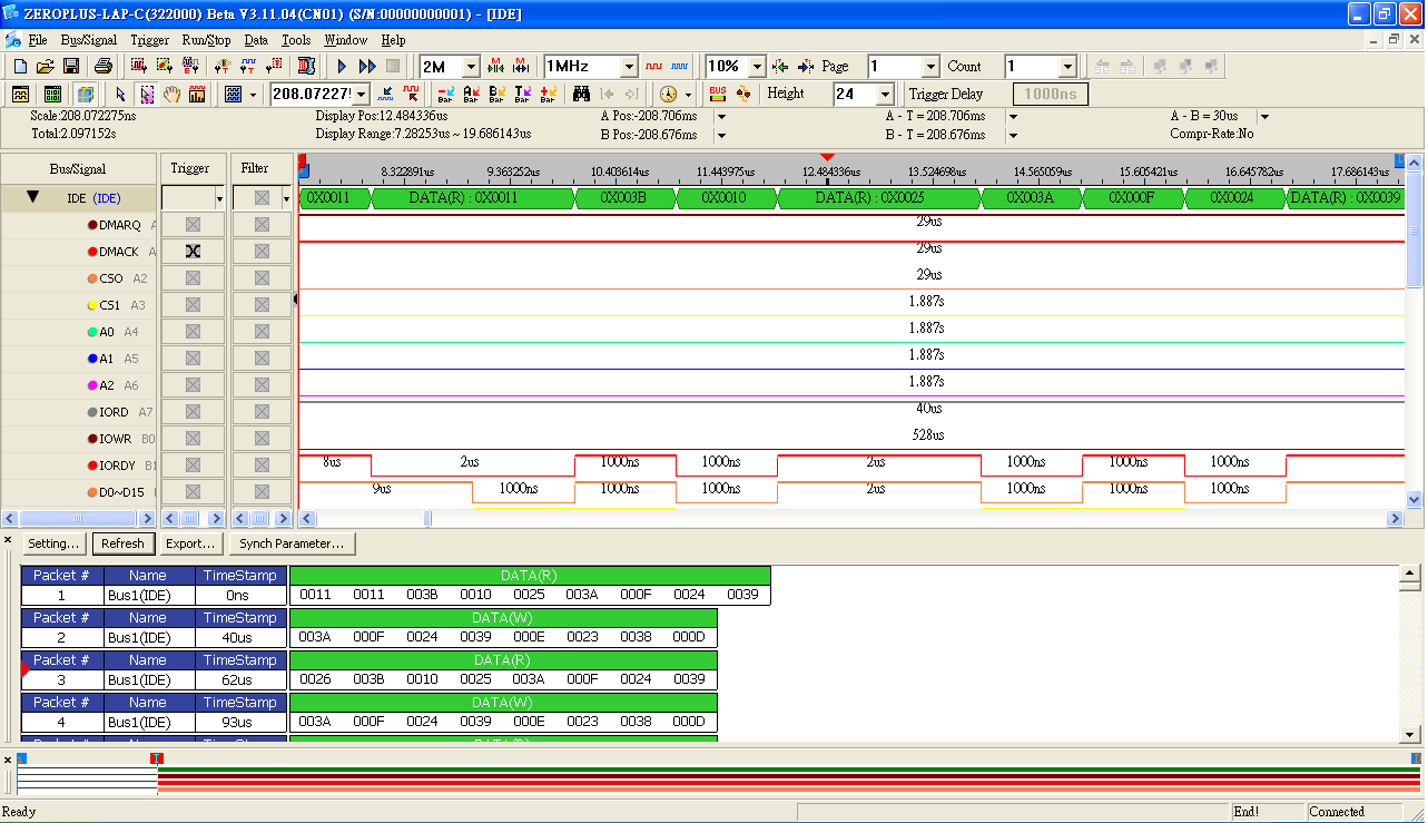
IDE(ATA) is a computer system interface; it is designed particularly for the desk computer. Traditional 40-pin parallel data line is used to connect it with the communication interface of mainboard, hard disk and CD-ROM. Since the technology of ATA controller and hard disk is developed, IDE(ATA) is classified into 7 ratings: ATA-1~ATA-7; each rating has its speed, which are 11.1MB/s, 16.6 MB/s, 33.3MB/s, 66.6MB/s and 100MB/s. 133MB/s is the largest speed of external interface. Low cost and high compatibility are its characteristics. |
|
|
 |
|
Low Pin Count is one kind of high-speed Bus made by INTEL company , In PC mainboard, it can instead of the used ISA BUS on the previous mainboard. With technology technic changing quickly, the data bit signals transmission are full of our daily life , but these signals should the relative exploitation tools ,to make the engineers complete the research work smoothly, so the Low Pin Count BUS is one kind of creating tool to provide to engineers. *Signal require higher sample rate, not support on LAP-C(16032)/(16064) |
|
|
 |
|
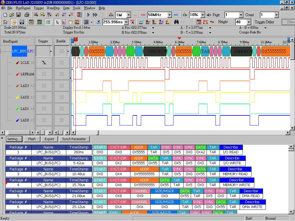
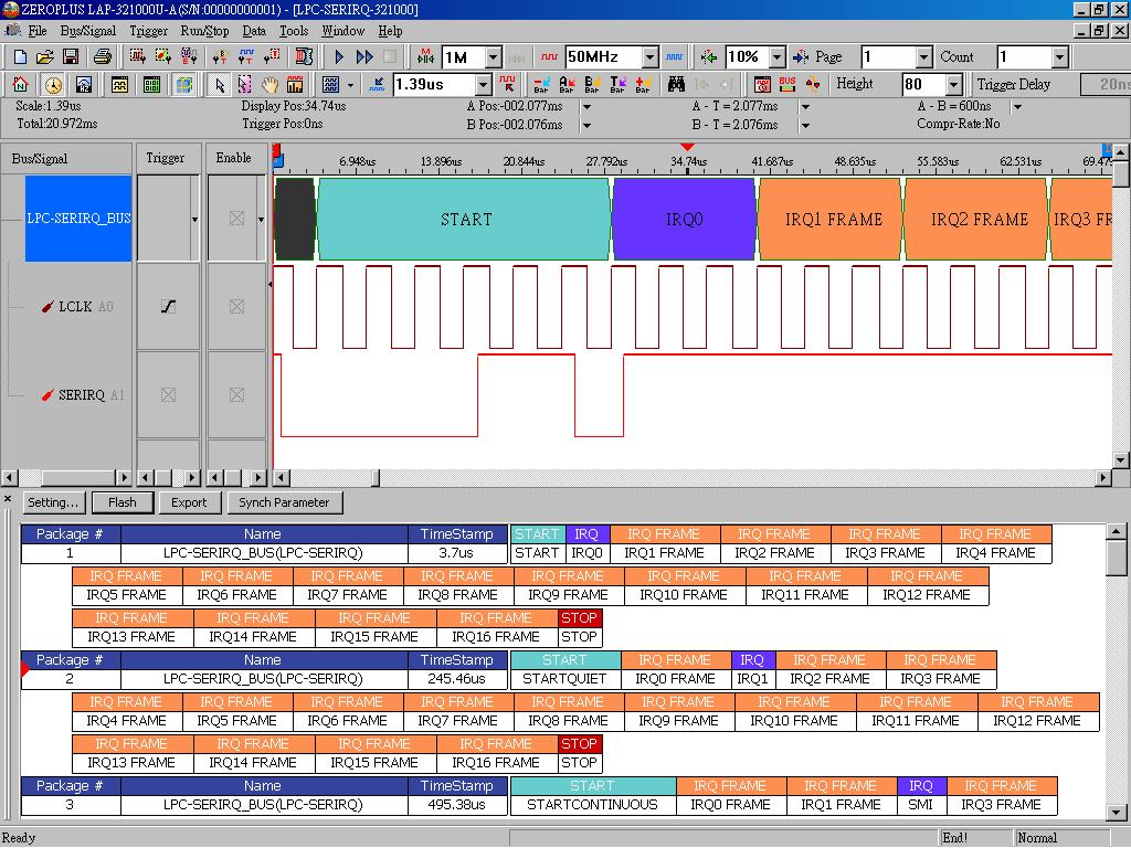
LPC BUS is one kind of high-speed and flexible interface which made by the INTEL Company , its frequency of CLOCK reaches 33MHz and only needs 7~13 channels interface to transmit data . It will be the future trend of development , the LPC Bus replaces ISA Bus of the tranditional mainboard in the mainboard structure. SERIRQ is one pin of LPC Bus system and is mainly used to execute the interrupted request. *Signal require higher sample rate, not support on LAP-C(16032)/(16064) |
|
|
 |
|
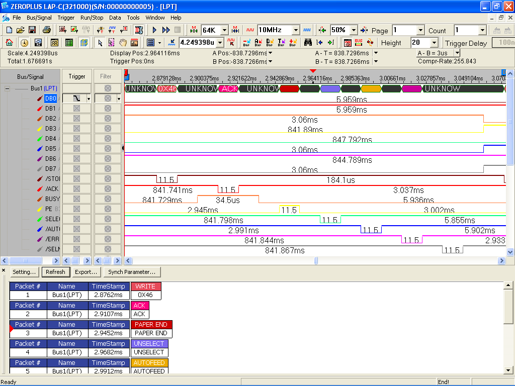
LPT (Line Print Terminal) is mainly used in computer peripherals, such as the Printer, Scanner or Modem and so on. And it utilizes the DB-25 Connector. Generally speaking, LPT has the following Working Modes: 1. SPP (Standard Parallel Port) Working Mode; 2. EPP (Enhanced Parallel Port) Working Mode; 3. ECP (Extended Capabilities Port) Working Mode; 4. BI–DIRECTION. However, in the four modes, the SPP Mode is the most widely used mode. |
|
|
 |
|
Zeroplus Logic Analyzer supports the function of analyzing Protocol Analyzer PCI. PCI (Personal Computer Interface) is widely used as a communication interface in the computer. Many great functions can be expanded in the computer by using the PCI interface. *Signal require 47 channels above, support LAP-F1-64 above; or link 2 sets of LAP-C(322000) above by channel extension . |
|
|
 |
|
Zeroplus Logic Analyzer supports the function of analyzing Protocol Analyzer PECI. PECI (Platform Environmental Control Interface) is a kind of Temperature Control used in CPU. It can supply the temperature of CPU for the system at real time to judge the operation efficiency of the heat-loss system. |
|
|
 |
|
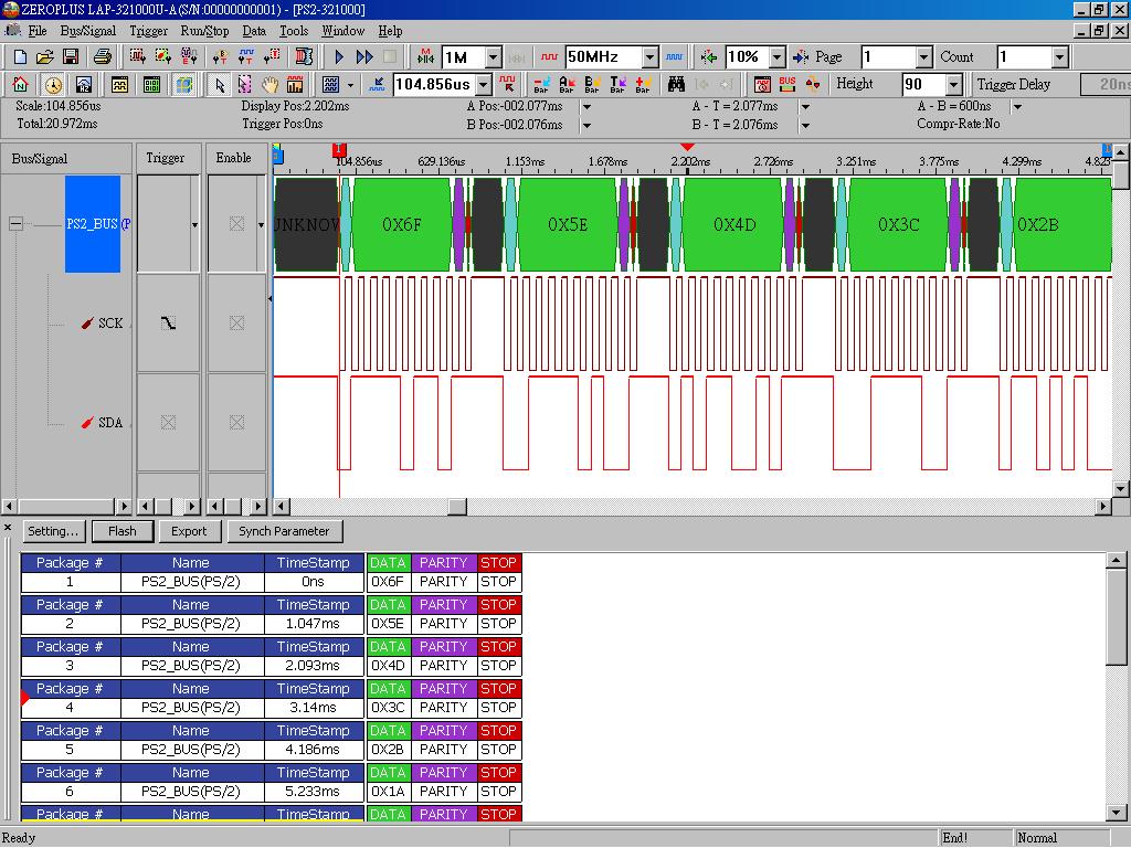
When engineers analyzed the data in signal, it takes a lot of time to find the crucial problem, which they looked for through counting waveform to recode to the signal. However, ZEROPLUS Logic Analyzer not only gathers all signals completely once but also auto code to the special bus coding software applied, moreover ,it can auto-display all bits in signal which are Start bit、Data bit、Parity bit、Stop bit、ACK bit. PS/2 interface is a very common connection interface, which is widely used in connecting PC Host and Mouse. |
|
|
 |
|
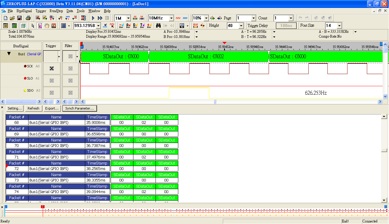
SGPIO, short for Serial General Purpose Input / Output, is a 4-wire signal transmission, it is mainly used in the signal communication between HBA (host bus adapter) and back panel. SClock, SLoad, SDataOut and SDataIn are its four control signals, the former 3 are transmitted from Initiator to Target, and the last one is on the contrary. |
|
|
 |
|
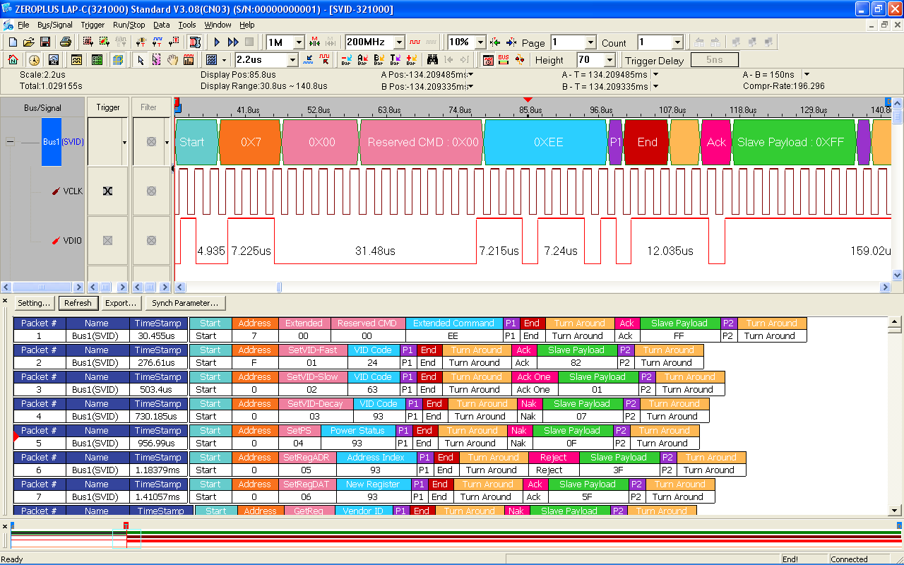
SVID (Serial VID) is a kind of the 3-line Serial Synchronous Transmission Interface, and the three channels are VCLK, VDIO and ALERT. It is mainly used for the Power Management in the Master-To-Slave Device, such as the Transmission between the Microprocessor and the Power Controller. And a Master Device can be connected with multiple Slave Devices through the SVID. |
|
|
 |
|
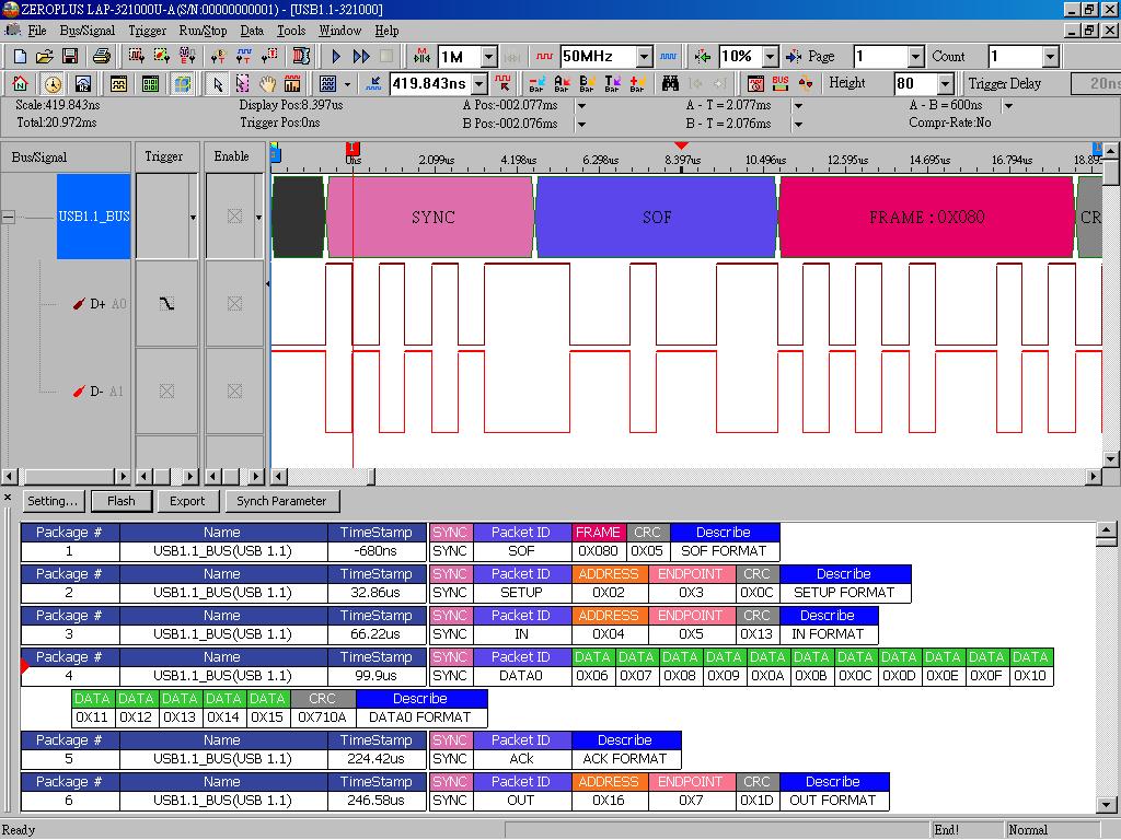
When engineers analyzed the data of signal, it takes a lot of time to find the crucial problem, which they looked for through counting waveform to recode the signal. However, ZEROPLUS Logic Analyzer not only completely gathers all signal once but also auto-codes to the supplied special bus encoding software. Moreover, the USB package function that supplied to analyze can help engineers achieve the aim to analyze bus easily. USB1.1 analysis tool, issued by Zeroplus Technology, matches with the special bus decoding module can greatly reduce the difficulty of test signal. |
|
|
 |
|
USB2.0 is a common interface. It has 4 Connect Lines, 2 for GND, the other 2 for signal (D+ and D-). Generally, the signals of two lines are opposite, if one line’s signal is High, the other line’s signal is Low. In this way it can improve its capability of anti-noise and anti-interference. USB just use such differential signal to transmit at a high speed. |
|
|
 |
|
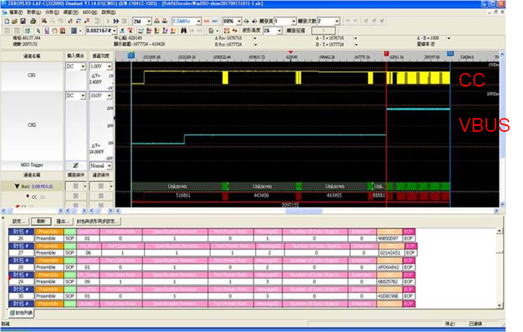
USB PD (Power Delivery) is designed to enable the maximum functionality of USB by dynamic sending Request message to change current and voltages over the cable so that provide more flexible power delivery along with data over a single cable. Previous USB support maximum output power is 7.5W, the USB PD up to 100W. |
|
|
|
|
|

 ProCision