|
IC Interface
 |
|
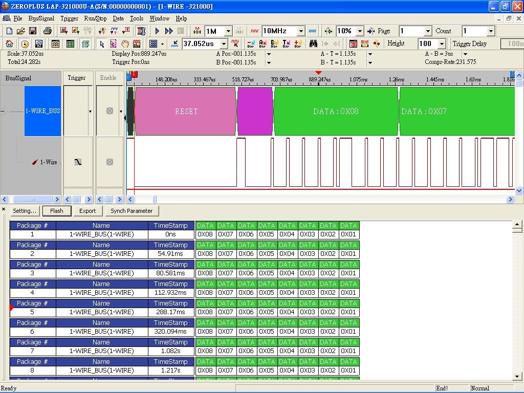
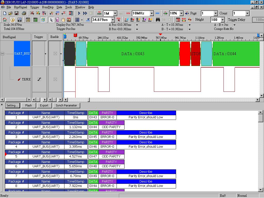
When engineers analyzed the data of signal,it takes a lot of time to find the crucial problem, which they looked for through counting waveform to recode the signal. However, Zeroplus Logic Analyzer not only completely gathers all signal once but also auto-codes to the supplied special Protocol Analyzer encoding software. Moreover, it can supply integrated signal format content of every data for you, the content includes RESET、PRESENCE PULSE and DATA. You can customize the number of data bit (the range is 1~32bit) and the sampling position (the range is 1~32bit), in order to let user read the data in package more exact. |
|
|
_EN01.png) |
|
Simple Introduction for Protocol Analyzer: ( 3 or 4 lines words) 1-Wire(Advanced) is designed by the Dallas Semiconductor and has one signal line, which can realize the functions of I2C and SPI. It can transmit the Clock and Data, and reach the dual-transmission. I-Wire uses the lower data transmission frequency, which is used for reading the EEPROM Interface. There are two kinds of frequency for 1-Wire that are STANDARD SPEED:15.4kbps and OVERDRIVE SPEED:125kbps. The common applications include the ID Identification of PCB, Sensor for medical treatment, IEEE-P1454 Sensor, ID Identification of Ink or Carbon powder clip and so forth. |
|
|
 |
|
Zeroplus Logic Analyzer supports the function of analyzing Protocol Analyzer 3-WIRE. It is mainly used on the sensor or the data transmission of clock chips. With the development of the science and technology, the transmission of the digital signal is glutting our daily life; however, those signals need the corresponding development tools to make engineers successfully finish the development work. |
|
|
 |
|
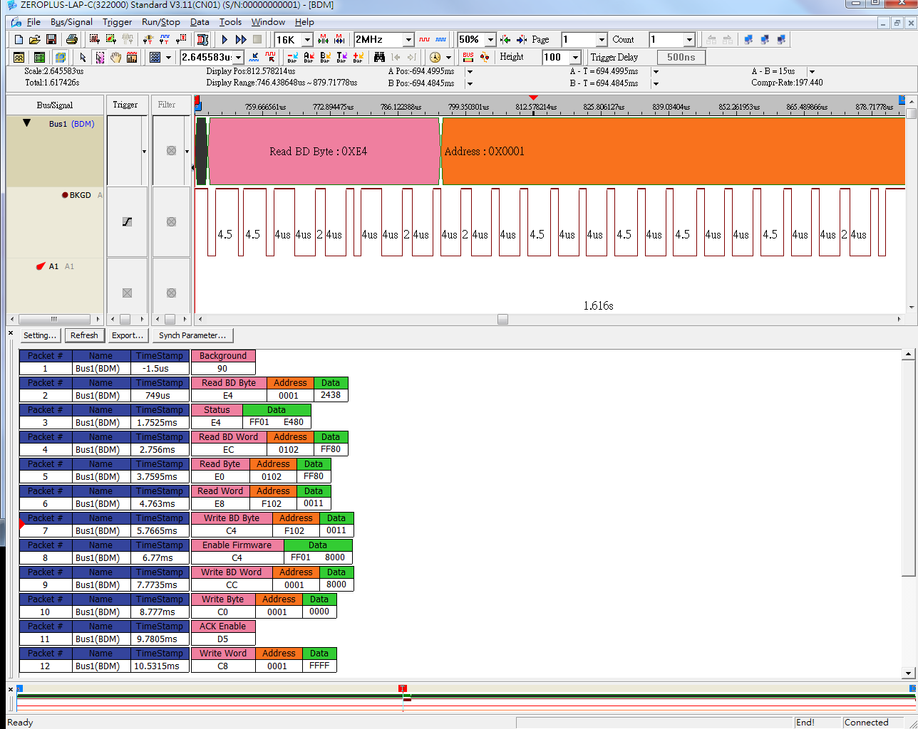
BDM (Background Debug Mode) is the signal interface which is used in the MCU or embedded system debugging. Currently it supports the majority of Freescale products, and can be used for system development, online debugging or programming, application download and online update. Because BDM control module is independent of the CPU, the BDM hardware command can be run with the CPU command concurrently. |
|
|
 |
|
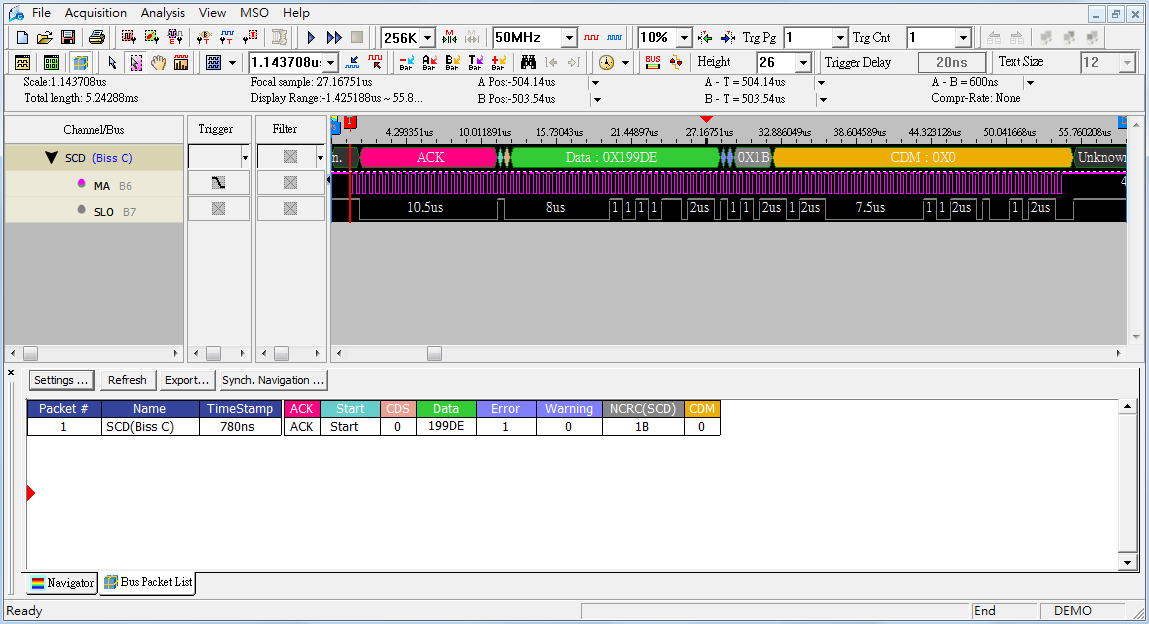
Developed by IC-HAUS, Biss provides a bi-directional fast communication standard for sensors and actuators, and is compatible with the industry standard SSI protocol. |
|
|
 |
|
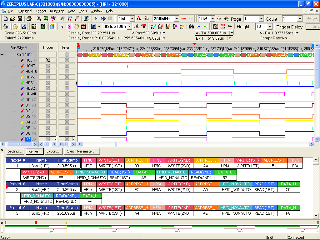
HPI (Host Port Interface) is a transmission interface, which is designed for DSP by TI (Texas Instruments). Hereinto, with the help of HPI, the DSP C5000 series and DSP C6000 series can be used to control all kinds of resources. Specifically, the HPI can be divided into two kinds, HPI-8 and HPI-16, which are used to transmit the 8-bit data and 16-bit data respectively. At the same time, the HPI-8 and HPI-16 can be divided into the Standard Type and the Enhanced Type. |
|
|
 |
|
When engineers analyzed the data in I2C signal or the presented errors during transmitting, it takes a lot of time to find the crucial problem, which they looked for through counting waveform to recode to the signal. However, Zeroplus Logic Analyzer not only gathers all signals completely once but also auto-code to the Protocol Analyzer coding software applied ,which helps engineers quickly arrive the aim to analyze Protocol Analyzer. It can help you reduce the time of developing signal and improve the efficiency of developing new product to use Zeroplus Logic Analyzer and bus auto-coding software. You can supply your correlated information for us;Zeroplus will make the customized bus analysis software for you as your requirement. |
|
|
 |
|
When engineers analyzed the data in I3C signal or the presented errors during transmitting, it takes a lot of time to find the crucial problem, which they looked for through counting waveform to recode to the signal. However, Zeroplus Logic Analyzer not only gathers all signals completely once but also auto-code to the Protocol Analyzer coding software applied ,which helps engineers quickly arrive the aim to analyze Protocol Analyzer. It can help you reduce the time of developing signal and improve the efficiency of developing new product to use Zeroplus Logic Analyzer and bus auto-coding software. You can supply your correlated information for us;Zeroplus will make the customized bus analysis software for you as your requirement. |
|
|
 |
|
The(JTAG:JOINT EUROPEAN TEST ACTION GROUP)was established by the Europe Institution in 1985, in order to research the test of volume circuit . After cooperating with the North American ,The name was changed into JTAG(JOINT TEST ACTION GROUP). The IEEE1194.1 testing interface and board scan structure [IEEE1149.1b 1194] were put out in base of JTAG 2.0 testing testing standards in 1990 , it also becomes the standards of ANSI(AMERICAN NATIONAL STANDARDS INSTITUTE ). With the development of the science and technology , the transmission of the digital signal gluts our daily life,however,those signals need the corresponding development tools to make engineers successfully finish the development work. It will help you to shorten the time of exploitation , improve exploitation products efficiency and unnecessarily add the instrument expense by using the Zeroplus Analyzer and Bus Automatic Decoding software . |
|
|
 |
|
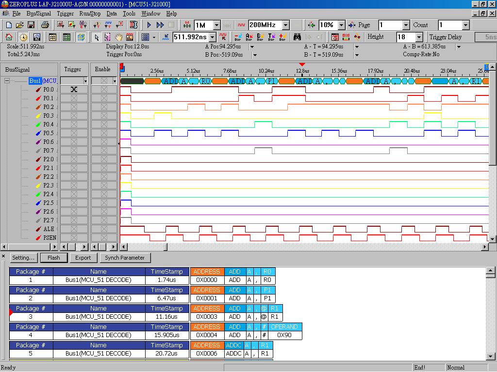
MCU-51 Protocol Analyzer micro control is a very common chip which has been learnt during the time or practice course of most engineer. You can analyze the status of MCU-51 connecting with extended memory through MCU-51 Protocol Analyzer of Zeroplus Logic Analyzer and learn the character and machine period of the dictate, especially the skip or or checking action of process enforcement from the result of analysis. With the development of science and technology, the transmission of digital sign has been flooding our life, while the engineer also need elative instrument tool of the sign to finish the exploration fluently. *Signal require 18 channels above, not support on LAP-C 16 channel series. |
|
|
 |
|
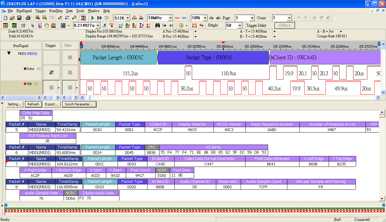
The MDDI interface standard is intended for portable imaging equipment regulated by group of VESA (Video Electronics Standards Association) under the image signal equipment. It is based on the LVDS transmission technology, supporting transfer rate is up to 3.2Gbps. Using MDDI interface can reduce the number of connecting the signal lines to six, generally two data lines, one is for Stb, another one is for DATA. If multiple data, one is for Stb, the data lines were DATA0, DATA1,and thus reducing the noise interference problem. |
|
|
 |
|
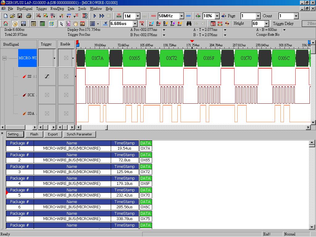
MicroWire is usually used in EEPROM, DAC (Digital-to-Analog Converters) and ADC (Analog -to- Digital Converters), thereinto its signal structure is quite similar to SPI (Serial Peripheral Interface). MicroWire transmits data by serial mode, so when user analyzes data, it takes a lot of time to look for the problem, which user looks for by counting the waveform to do signal coding, and the process has to use oscillograph. However, as to ZEROPLUS Logic Analyzer,it not only completely gathers the data once ,but also auto-decodes by the applied special bus coding software. |
|
|
 |
|
SDI-12 is a low-speed serial data protocol primarily used for environmental sensors. Use a data cable for bidirectional communication, supporting connections between multiple sensors and data loggers. |
|
|
 |
|
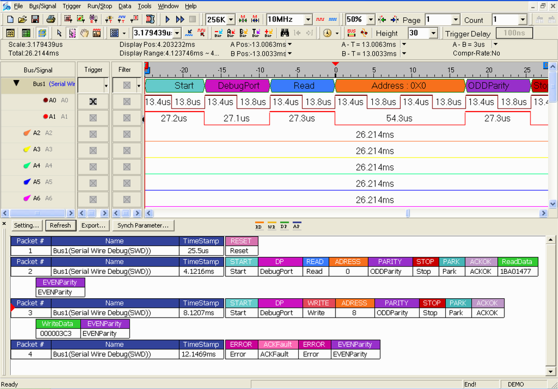
Serial Wire Debug(SWD) is to complement the JTAG.. It provides all debugging and testing functions of JTAG and the way to access the memory. Using the ARM Standard Two-wire Protocol, it provides the debugger and the high-efficient/standard transmission mode in the target system. Debugging, high transmission rate (50MHz), low power and low cost are its advantages. |
|
|
 |
|
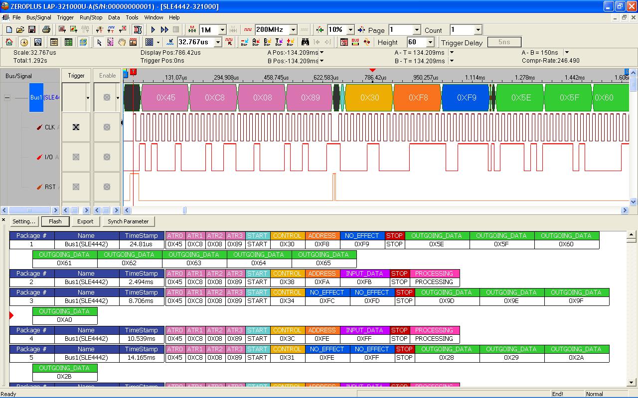
Zeroplus Logic Analyzer supports the function of analyzing Protocol Analyzer SLE4442. The names of SLE4442 and SLE4443 may be unfamiliar to a part of engineers, but they are used on the IC of Smart card; the familiar application of them is in finance cards, credit cards, health insurance cards and so forth. |
|
|
 |
|
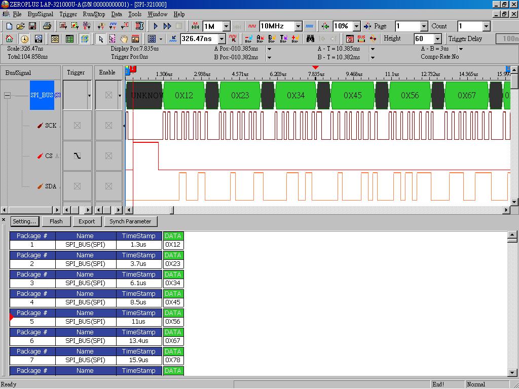
Generally SPI Protocol Analyzer shows in two groups of data when it is used, the two groups of data are DATA IN/MISO and DATA OUT/MOSI;If enginee test signal with the normal two-channel oscillograph, it must need to test more than twice. First, we test MOS part, connect CS to EXTTRIG as trigger signal, then connect CH1 to DATA and CH2 to SCK, next test the MISO by the same step. If it need test MOSI again, the oscillograph should be connected again. |
|
|
 |
|
The Protocol Analyzer SPI is usually displayed with two groups of data mode (DATA IN/MISO and DATA OUT/MOSI) when it is used. If engineers use the most common oscillograph with two channels to measure the signal, they need to measure the signal more than two times. Firstly,they need to measure the MOSI part. When they measure the MOSI part, they need to connect the CS to EXTTRIG to work as the trigger signal, then connect the CH1 to DATA and CH2 to SCK. Secondly, they need to measure the MISO part according to the method of measuring the MOSI part. If engineers want to measure the MOSI part again at the moment, they need to connect the oscillograph to the original state. Obviously, it wastes a lot of time with the complex steps. |
|
|
 |
|
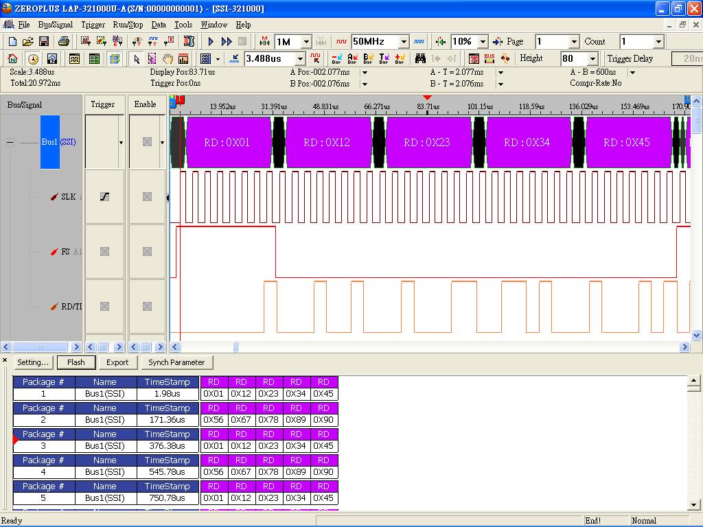
The familiar usage range of SSI Interface includes wireless communications transmission (instead of the company,such as MOTOROLA、NOKIA)、servo power management 、ADC transition、DAC transition and multimedia digital signal decoding (CODECS) and so on. |
|
|
 |
|
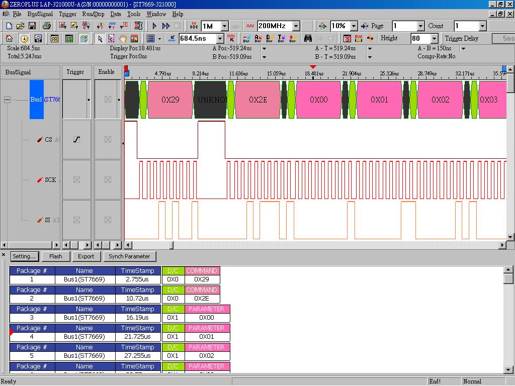
ST7669 chip is developed by Sitronix, it is appliein module of LCD screen. Excellent design of ST7669 can help user save electrical energy and provide user with better performance. Technology is advancing very quickly, transmission of numerical signal is already very common in our daily life, However, engineers can smoothly finish development work on condition that the signals need corresponding development tool. |
|
|
 |
|
When engineers encoded signal with oscillograph , it only saw the shaking waveform of the signal , user not only captures the signal repetitively but also counts to get the data, at this time, if user use ZEROPLUS Logic Analyzer, because of the multi-channel characteristic, ZEROPLUS Logic Analyzer can completely gather all signal once; and through ZEROPLUS Special bus auto-coding function, user can get the data value quickly and breezily without counting and analyzing by themselves. |
|
|
|
|
|

 ProCision