Logic Analyzers-Zeroplus


  youtube facebook twitter  
  Instrument Division
繁體中文 / 简体中文 / English  

Software

>> Signal Process Home / LAP-F1 ZP-Logic /
  Software quick application note
Trigger Function
 Signal Process
 Optional function
 Other

Latch Function

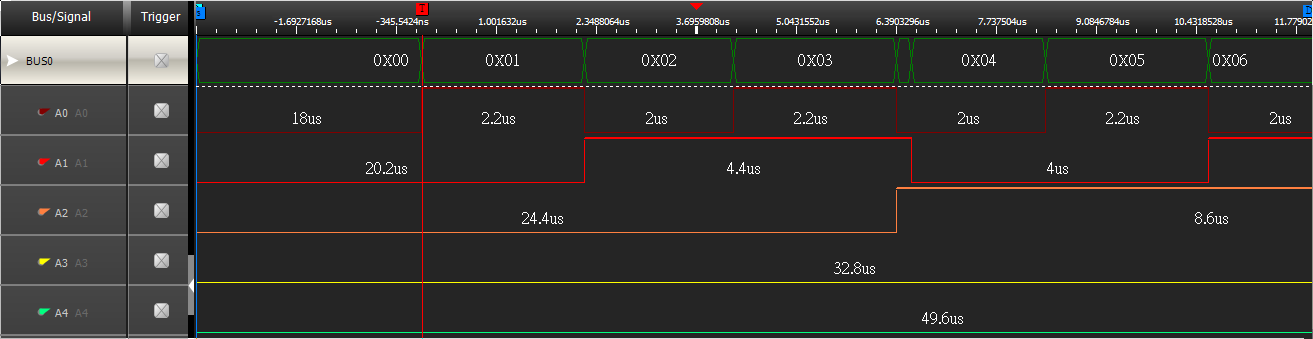
Users can set the specified signal in the paralleling bus as the sampling site reference to analyze the data.

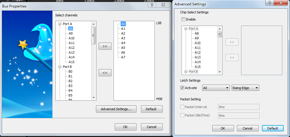
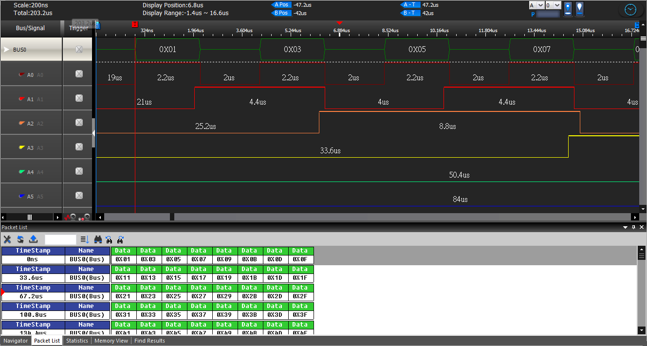
In the Latch setting window(see figure 2), users can activate the Latch function and set its channel and condition (Rising Edge, Falling Edge, Either Edge), then click OK. The analysis result will be displayed in the waveform display area.

before Latch Function

Figure 1:before Latch Function


Latch setting window


Latch setting window

Figure 2:Latch setting window


For example: If some signal under test is 7 bits paralleling bus, And the data A0 rising edge Latch data, See figure 3 for the result after setting finished.

Analyze with Latch function

Figure 3:Analyze with Latch function.


Copyright ZEROPLUS TECHNOLOGY CO., LTD.